Autodesk provides a RichAuto DSP post processor for Fusion, but selecting its name is only the start of checking a machining program. The post translates CAM operations into controller instructions; it does not identify the wiring, work origin, tool-change arrangement or settings of your particular machine. Review the exported NC file against those requirements before physical execution.
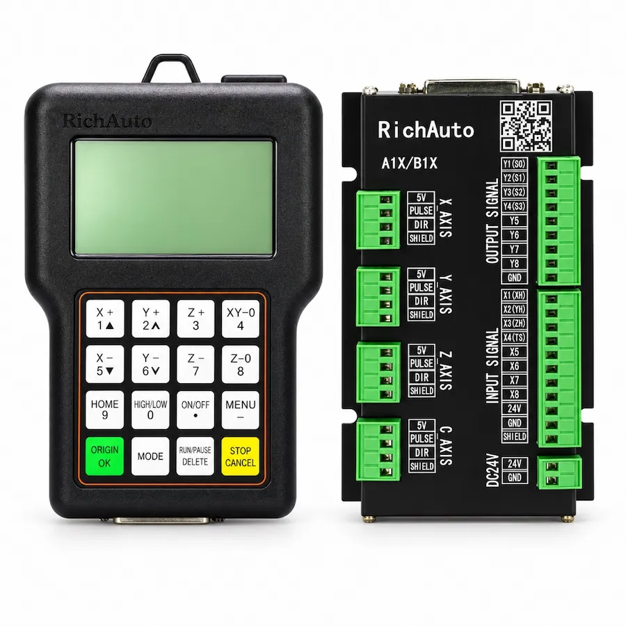
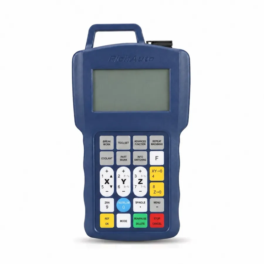
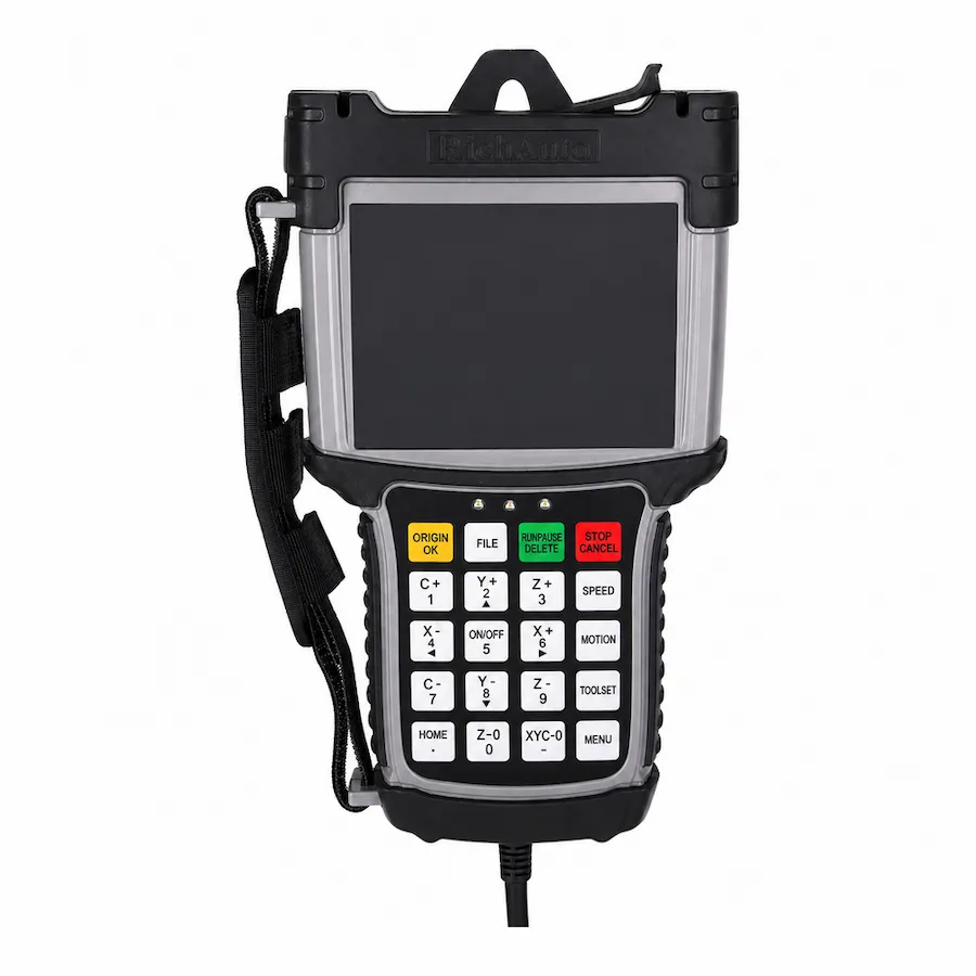
This guide focuses on conventional three-axis workflows associated with A11, B11 and B51. A program still needs to match the controller settings and machine configuration before it is ready to run. Four-axis and automatic tool-changing arrangements need additional, machine-specific consideration.
What a Post Processor Does
A CAM toolpath describes intended movements and operations inside the software. A post processor converts that information into the syntax and conventions expected by a controller. It can determine output units, coordinate instructions, arc representation, spindle commands, retracts and tool-change instructions.
The resulting NC file contains machine instructions and is separate from the Fusion design or CAM project. Copying the design file to a USB drive does not create a machine program. Similarly, changing a file extension does not translate instructions into a different controller dialect.
Three things must agree: the CAM setup, the selected post and the machine configuration. A correct cutter path can still produce unsuitable output if the post requests an unsupported coordinate operation. A suitable post can still produce an incorrect job if the stock origin or units are wrong in the setup.
Check the Autodesk RichAuto DSP Entry
The Autodesk RichAuto DSP post entry provides a generic milling post. It outputs an NC file using ASCII text, restricts circular interpolation to the XY plane and provides work-offset mapping for G54 through G59. It also rejects multi-axis machine configurations.
That limitation matters for RichAuto model selection. A18, B18 and B58 are four-axis controllers, but sharing the brand with a three-axis controller does not make the generic post suitable for their rotary jobs. Removing a software error or changing a machine definition to three axes does not create the missing rotary output.
Record the post revision you use. Library updates and local edits can change output behavior, so a program generated with another copy is not necessarily an identical comparison. Keep a reproducible record with the CAM setup and exported file when investigating an issue.
Confirm the Machine Scope Before Posting
Identify whether the job uses ordinary XYZ motion, an indexed rotary position or simultaneous rotary movement. The last two require a post and machine setup that represent the additional axis correctly. Do not hide a rotary requirement merely to complete an export.
Next, identify tool handling. A manually changed router may need separate programs or planned operator stops; an ATC router requires output that agrees with the configured automatic sequence. A generic tool call cannot define where a magazine is located, which holder belongs in each position or whether a release sensor is satisfied.
Also record the controller’s software version and its relevant program settings. For example, the A11 operating reference, in its G-code setup section, describes settings affecting whether certain program instructions are read or ignored. Those are version-specific examples of why the program and controller settings need to be checked together.
Match Units and the CAM Work Origin
Confirm the intended units in the CAM setup, the post settings and the resulting program. A coordinate value only has meaning with its unit. Do not assume the software display units alone establish the units emitted by the post or used by the installed controller.
Check where the CAM origin is placed: a stock corner, center, finished surface or another chosen reference. The machine’s active work origin must represent that same point. A valid program can move to the wrong place if its intended stock location and the controller’s selected reference differ.
Review the first positioning movements and the overall job extents. Do they agree with the stock dimensions and setup orientation? This comparison can reveal an unexpected origin, scale or axis direction before the cutter approaches material. It should be made together with the machine’s available travel and fixture positions.
Understand Work-Offset Instructions
A work offset relates program coordinates to the part’s position on the machine. If the post outputs a work-offset command, confirm how the installed controller handles it and how that relates to the selected work-coordinate location on the handheld.
Do not assume that a coordinate number shown in one interface has the same meaning as a CAM work-offset setting. Establish the mapping using the operating instructions and a reviewed setup. A program that selects one reference while the operator prepared another can be syntactically valid and still be wrong for the job.
Avoid combining unexplained offset adjustments with a changed CAM origin. If the work moves, update the setup through a deliberate procedure. Preserve the distinction between the machine reference, the part reference and the tool reference; the A11 homing and work-zero guide explains those relationships.
Review Retracts Against Real Clearances
Autodesk’s RichAuto post offers different retract approaches, including clearance-height and machine-reference-based options. Each has prerequisites. A clearance height must clear the stock, fixtures and travel route. A machine-coordinate movement depends on correctly established machine referencing and supported instructions.
There is no universal retract choice for every RichAuto installation. Determine what the output actually commands at the start, between operations, during a tool change and at the end. Compare those movements with the machine’s homed state, work position and obstacles.
For example, a height that clears the part surface can still intersect a tall clamp. A tool-change movement can also require more clearance than an ordinary cutting retract. Review the complete route rather than checking only the Z value on the first operation. Do not suppress a retract warning without understanding the condition it describes.
Check Arcs, Feeds and Spindle Behavior
Inspect curved moves and the plane in which they occur. The generic post’s circular-output scope does not mean all curved toolpaths will appear as the same instruction. The CAM strategy, post and controller interpretation need to agree on how the curve is represented.
Review feed commands, rapid positioning and spindle commands separately. Feed controls the intended cutting movement; a spindle speed value represents a separate request. The installed controller and spindle system must interpret that request appropriately. On a machine with discrete spindle-speed selection, a numeric speed in the file alone does not establish continuous RPM control.
If a previously accepted job runs differently after a new export, compare the relevant instructions and post settings before changing machine parameters. A changed toolpath, feed mode or spindle command can explain the difference without any failure in USB transfer.
Treat Tool Changes as a Machine Requirement
The presence of a tool-change instruction in post output is not an ATC compatibility certificate. Check whether the machine expects an operator action, a separate program or a configured automatic sequence. Tool numbering and tool-length references must agree with that arrangement.
For a manual router, review how the job stops, how the next cutter is identified and how its Z reference will be established. A deliberate single-tool export can make this easier to review, but the split must preserve the intended work coordinates and operation order.
For B57, obtain the machine builder’s output requirements and validate the complete tool-change sequence. Do not use a generic multi-tool export as evidence that the magazine, holders and sensors are configured correctly. The B51 vs B57 comparison explains why the tool-changing architecture is a separate decision from ordinary three-axis motion.
An NC Output Review Sheet
The fragments below are recognition examples, not a complete program or instructions to run a machine. Their support and meaning must be checked for the installed controller.
Scroll horizontally to read all columns.
| Output feature or example | Question to answer before execution |
|---|---|
Unit selection, such as G21 |
Do setup, output and controller interpretation use the same units? |
Coordinate mode, such as G90 |
Are the positions expressed in the intended mode? |
Work selection, such as G54 |
Does this correspond to the reference prepared on the machine? |
Spindle request, such as an S value with M3 |
How does the installed spindle system interpret start and speed? |
Tool request, such as a T number with M6 |
What physical or operator sequence is expected? |
Circular move, such as G2 or G3 |
Are plane, arc format and controller interpretation suitable? |
| Retract and end movements | Do they clear fixtures and use a valid reference? |
Compare the output with a previously accepted program from the same machine, while recognizing that the new job may need different commands. Keep the comparison focused on meaningful differences rather than assuming every line must match.
Check the Program Before a Machine Trial
Save the CAM setup, post revision, settings and output together. Review units, coordinates, tool handling, retracts and job extent before transferring the file. Then confirm the loaded filename and selected work location at the machine. USB detection is a separate check covered in the USB file-reading guide.
A qualified operator should use the machine’s established commissioning and program-proving procedure for physical testing. Software simulation and successful file loading help identify issues, but they do not confirm actual clamps, tool retention or spindle behavior. Record any message with its program line and preserve the file that produced it.
If a change is needed, identify whether it belongs in the CAM setup, post settings or machine configuration. Change one understood element, regenerate the output and review the affected movements again. That creates a traceable route from a Fusion operation to a RichAuto program suitable for the particular machine.