


BEST FIT
Choose B11 if:
- The machine uses conventional three-axis motion.
- The current B1X display and I/O suit the operating needs.
- The matching board and drive signals can be installed as a system.
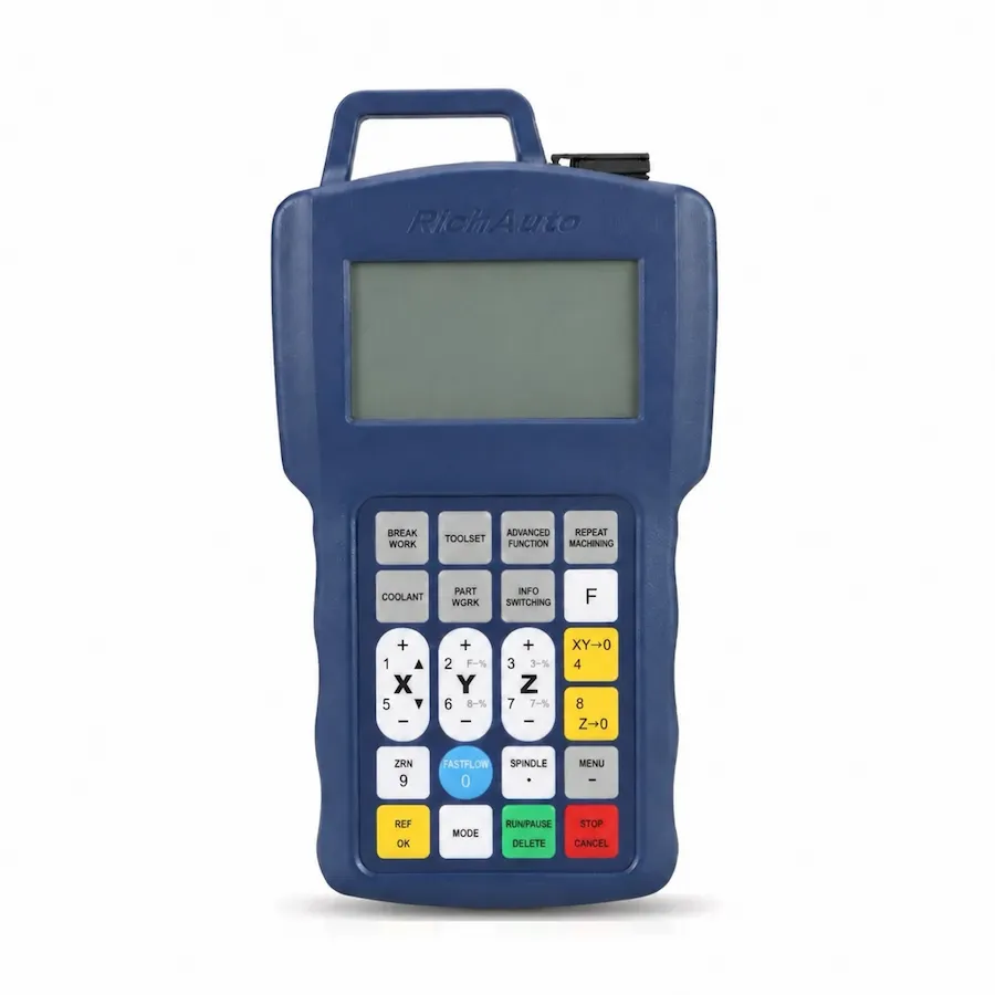
RichAuto B11 handheld controller front panel and keypad. Reference photo; confirm the supplied controller and interface-board revision.
B1X SERIES · RA-B11
Three-axis B1X DSP control for routing and engraving, selected around the machine interface and required file-transfer workflow.
Series: Browse the B1X controller range
CINKR supplies new, genuine RichAuto controllers and supports single-unit replacement orders. Eligible faults are covered by a one-year warranty. Most orders are dispatched within three working days after payment.
The supplied components, configuration, shipping cost and delivery estimate are confirmed in your quotation. Delivery, warranty and return terms.
PRODUCT GUIDE
Three-axis B1X DSP control for routing and engraving, featuring 4.3-inch color LCD display, differential drive signals and advanced curve interpolation.
QUICK DECISION
BEST FIT
CHECK BEFORE ORDERING
CONSIDER ANOTHER MODEL IF
The RichAuto B11 represents the second-generation B1X motion control architecture engineered for high-precision three-axis CNC routing, relief carving, and mold engraving equipment. Building upon the proven reliability of handheld standalone systems, the B11 integrates a vibrant 4.3-inch color liquid crystal display, high-speed 2.0 MHz differential pulse generation, and advanced continuous curve smoothing algorithms.
Machining complex contoured surfaces in wood, brass, acrylic, and composite tooling board demands smooth acceleration transitions between micro-segments. The B11 motion engine calculates predictive look-ahead trajectories that suppress mechanical vibration, resulting in noticeably superior surface finishes and reduced hand-sanding time on finished components. By generating differential pulse trains, the controller remains immune to severe electromagnetic noise radiated from adjacent spindle inverters and servo drives. For machine retrofits or new equipment designs, request a B11 quote configured for your motor drives.
Each standard RichAuto B11 control package arrives complete with industrial components intended for electrical cabinet mounting:
Inspect all terminal blocks and cable strain relief boots upon receipt to ensure physical integrity before cabinet mounting.
The 4.3-inch color display of the B11 transforms everyday machine floor operation:
The intuitive menu structure reduces operator training overhead and minimizes setup mistakes during coordinate zeroing. To discuss network infrastructure or multi-station clamping parameters, connect with CINKR technical specialists.
Cabinet wiring for the B11 terminates at the B1X intermediate interface board. The board utilizes organized screw terminal blocks providing robust isolation:
| Terminal Group | Terminal Identification | Connected Signal | Electrical Specification |
|---|---|---|---|
| Power Input | 24V+, GND | Primary cabinet logic supply | 24V DC regulated, 2A minimum |
| X Axis Differential | X_PUL+, X_PUL-, X_DIR+, X_DIR- | Differential step and direction lines | High-speed 5V RS-422 differential driver |
| Y Axis Differential | Y_PUL+, Y_PUL-, Y_DIR+, Y_DIR- | Differential step and direction lines | High-speed 5V RS-422 differential driver |
| Z Axis Differential | Z_PUL+, Z_PUL-, Z_DIR+, Z_DIR- | Differential step and direction lines | High-speed 5V RS-422 differential driver |
| Digital Inputs (1-16) | IN01 through IN16 | Limits, home sensors, tool touch plate | Optically isolated 24V NPN sinking inputs |
| Digital Outputs (1-16) | OUT01 through OUT16 | Inverter run, coolant, vacuum, dust hood | 24V open-collector transistor outputs |
| Handwheel Interface | MPG Channels | Manual pulse generator quadrature input | 5V differential AB-phase encoder input |
Differential signaling significantly enhances noise immunity across long gantry cable tracks, preventing step loss caused by high-power spindle motor electrical noise.
The core processing kernel of the B11 features advanced trajectory look-ahead planning:
These motion planning features deliver substantial productivity gains when machining complex wooden relief panels, architectural moldings, and brass stamping dies.
In procurement channels and machine documentation, the controller appears under designations such as B11, B11E, B11S, or B11C. These variations specify the keypad language silk-screening:
| Model Marking | Keypad Faceplate Language |
|---|---|
| B11 | Base B1X 3-axis motion platform |
| B11E | English-only keypad faceplate (Export standard) |
| B11S | Bilingual (Chinese + English) keypad faceplate |
| B11C | Bilingual (Chinese + English) keypad faceplate |
All 4.3-inch color LCD display functions, 2.0 MHz differential pulse outputs, 16I/16O terminal boards, and spline interpolation firmware are identical across B11, B11E, B11S, and B11C. The only distinction is the silkscreen language on the physical keypad buttons. When selecting a unit for your shop floor, match the physical breakout board terminal layout, then submit an equipment inquiry.
Maximizing machining efficiency on the B11 platform relies on disciplined tool touch-off routines and multi-fixture coordinate offsets:
Establishing verified tool offset procedures minimizes setup time and ensures flawless surface depth repeatability across production runs.
Diagnostic messages displayed on the color screen guide rapid fault isolation:
| Screen Diagnostic | Underlying Fault Condition | Verification Procedure |
|---|---|---|
| Hard Limit Activated | Axis carriage contacted physical overtravel microswitch | Inspect sensor LED indicator; verify limit switch wiring continuity |
| Spindle Alarm Input | Frequency inverter tripped on overcurrent or overload | Read inverter display panel error code; verify cooling fan operation |
| Pulse Frequency Error | Commanded feedrate exceeds 2.0 MHz pulse threshold | Check pulse equivalent settings and maximum rapid traverse parameters |
| USB Read Timeout | Loose drive connection or non-FAT32 file system | Reseat USB thumb drive; verify drive is formatted FAT32 under 32 GB |
| Emergency Stop Engaged | External E-stop button depressed or safety relay tripped | Measure 24V continuity across safety circuit input terminals |
Regularly verifying physical cable shield terminations prevents intermittent communication alarms in production shops.
Facilities upgrading older three-axis machines from the A11 to the modern B11 must plan for cabinet modifications:
Our engineering team can evaluate your cabinet wiring schematics and provide a step-by-step upgrade plan.
To determine the ideal three-axis platform for your facility:
SELECTION CHECKLIST
SPECIFICATIONS
Compare the current B1X platform below. For an existing machine, match the controller label, interface board and software version; reference documents and photos may show earlier hardware.
| Product model | B11 |
|---|---|
| Series | B1X |
| CPU | DSP |
| Internal memory | Ask CINKR for the memory capacity of the supplied controller. |
| Display | 4.3-inch |
| Communication | USB / TCP/IP |
| Controlled axes | 3 axes |
| Control signal | Differential |
| Drive system | Stepper / Servo — Match the supplied hardware and software version. |
| Inputs | 16 inputs |
| Outputs | 16 outputs |
| Additional I/O | Confirm the board variant and available terminals for additional I/O. |
| Minimum input unit | 0.001 mm |
| Max. pulse frequency | 2 MHz |
| Power supply | 24V DC — Interface-board input; check its rating separately from the handle supply. |
| Interpolation | Request the interpolation details for the supplied software. |
| Breakpoint resume | Request the operating instructions for the supplied B1X software. |
| Power-failure recovery | Request the recovery instructions for the supplied B1X software. |
| Soft / hard limit | Confirm the limit and protection configuration with the machine builder. |
| Password protection | Request the protection and access settings for the supplied software. |
| Rotary axis | Not supported |
| ATC support | Not supported |
| Multi-spindle / cylinders | Not supported |
| Plasma control | Not supported |
| Handwheel / MPG | Supported |
| Network communication | Supported — Match the supplied network interface and transfer workflow. |
COMPARE RELATED CONTROLLERS
Compare current platform applications, axes, display and I/O. Match the supplied board before replacement; earlier hardware may differ.
| Model | Main use | Axes | Display | I/O | Relationship |
|---|---|---|---|---|---|
| B11 | Three-axis routing and engraving | 3-axis | 4.3-inch | 16 inputs / 16 outputs | Selected model |
| A11 | Three-axis routing and engraving | 3-axis | 3-inch | 8 inputs / 8 outputs | Same-class option — compare functions, wiring and signals. |
| B51 | Three-axis routing with color preview | 3-axis | 5-inch | 16 inputs / 16 outputs | Same-class option — compare functions, wiring and signals. |
B11 alternatives depend on the required motion and machine functions. A related model is not a promise of interchangeable wiring or firmware.
DOWNLOADS
Download reference documents below. Match the controller and interface-board revision before using any wiring instructions. For a replacement or new order, request the documents for the exact supplied hardware from CINKR.
Reference wiring diagrams with English labels and signal notation. Confirm the matching board revision before using them.
Free direct downloadReference instructions and parameter guidance, mainly in English with some Chinese labels. These reference editions may describe earlier hardware; the supplied unit must match the document.
Request the matching files for your hardware revision.FAQ
The B11 platform introduces a 4.3-inch color LCD screen, enhanced spline curve interpolation for superior surface finish, differential step and direction driver signaling (2.0 MHz max pulse frequency), and expanded 16-input / 16-output terminal blocks, compared to the 3-inch monochrome common-anode A11.
Yes, but the upgrade requires installing both the B11 handheld pendant and its corresponding B1X intermediate breakout board. Because the B11 uses differential pulse signals and a different cable pinout, the existing A11 breakout board and 50-pin cable cannot be reused.
Yes. The B11 interface architecture supports standard manual pulse generator (MPG) handwheels for precision manual axis positioning and workpiece setup.
B11E designates the English-language export version of the B11 controller, incorporating English keypad buttons and default English system menus. Internal motion logic and hardware specifications are identical.
Yes. Both models feature the exact same high-resolution color LCD screen, graphical coordinate displays, and menu navigation architecture.
Yes. Both connect to the standard B1X intermediate interface board utilizing differential step and direction driver terminals.
Yes, but the cabinet breakout board and 50-pin cable must be replaced together, as the B11 series uses differential signaling rather than common-anode buses.
REQUEST A QUOTE
Tell us the quantity and destination country. For a replacement or upgrade, include any available machine details below. This form only prepares your message; nothing is submitted or stored.