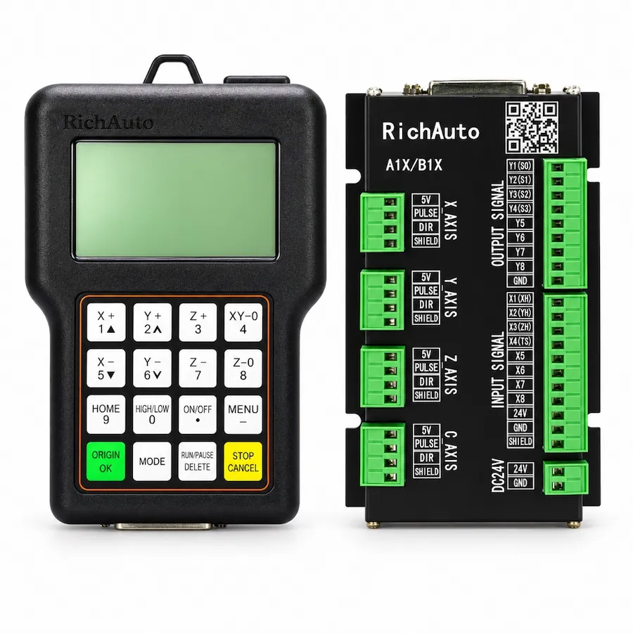
On a RichAuto A11, homing, setting work zero and tool setting perform different jobs. Homing establishes the machine’s position reference. Work zero locates the programmed part on the machine. Tool setting establishes the cutter reference needed for the intended Z positions. A correct result depends on their relationship, not simply on seeing zeros on the handheld display.
If a job starts in the wrong place or cuts to the wrong depth, identify which reference changed before adjusting parameters. This guide explains the concepts and a diagnostic order. Follow the machine’s documented operating procedure for actual movements, buttons and tool-setting equipment; do not transfer a shortcut from another A11 generation without checking it.
Three References, Three Different Questions
- Machine referenceWhere is the axis within the machine's travel?
- Work referenceWhere is the program's origin on this part?
- Tool referenceWhere is this cutter's tip relative to the chosen Z reference?
The machine reference gives the controller a basis for locating motion within the machine. The work reference connects program coordinates to a chosen point on the material or fixture. The tool reference accounts for the cutter being used. Changing the cutter can affect the third relationship even when the fixture and machine reference have not moved.
The A11 operating reference covers returning home, coordinate systems and tool-setting parameters in separate sections. It is a useful explanation for the version it describes. Confirm the instructions for the installed unit before using any specific menu entry or automatic tool-setting function.
What Homing Establishes
The home routine uses the configured machine reference system, including the relevant sensing and motion settings. It is intended to establish repeatable axis positions within the machine coordinate system. The home direction, sequence and offset are machine configuration matters; they cannot be inferred solely from the controller’s model name.
Homing does not measure the dimensions of the material, find a drawing’s stock corner or establish the length of a newly fitted cutter. Those require other setup information. A machine can therefore complete its home routine while the work origin is still wrong for the loaded job.
Before homing, follow the machine’s preparation procedure and confirm that the expected route is unobstructed. If an axis moves in an unexpected direction, fails to detect its switch or does not stop as expected, interrupt the operation through the machine’s controls. Repeated attempts do not repair an incorrect sensor state or home configuration.
Do not confuse homing with resetting the controller. A factory or parameter reset can change the setup needed for correct motion. The safe reset guide addresses that separate maintenance task.
What Work Zero Establishes
The work origin is the reference chosen for the program: it could be a stock corner, the part center or a fixture location. The CAM setup determines how programmed positions relate to that reference. At the machine, the active work-coordinate location must represent the same point and orientation.
The controller can show machine positions and work positions differently. A zero in a selected work system does not mean the axis is at the machine’s home reference. Likewise, changing the selected work location can change the displayed values without physically moving the part.
Before a new job, confirm which work location is active, where the CAM origin sits and how it was established on the machine. If several jobs or fixtures use stored locations, label the setup records clearly. Selecting the wrong stored reference can shift every movement by a consistent amount even when the program itself is correct.
Tool Setting and the Z Reference
Tool setting establishes a usable reference for the cutter tip through the machine’s configured procedure. With manual tool changes, the projection of the next cutter may differ from the previous one. Reusing an old Z reference without accounting for that difference can change the cutting depth.
Where a tool-setting plate or gauge is used, its dimensions and the controller’s corresponding settings matter. A plate-thickness value must represent the actual gauge used by that procedure. Do not substitute a number found online or assume that all machines use the same plate arrangement.
The reference surface also matters. Setting Z from the material top and setting it from the spoilboard are different workflows. Both can be deliberate choices, but the CAM setup and machine setup must use the same relationship. Tool setting confirms a reference; it does not decide which reference the CAM designer intended.
A Worked Example: Material Top vs Spoilboard
Consider a hypothetical 20 mm thick workpiece. The values below illustrate coordinate relationships only; they are not a machining program or a machine parameter recommendation.
Scroll horizontally to read all columns.
| Setup choice | Material top in the program | Spoilboard in the program | A point 5 mm below the material top |
|---|---|---|---|
| Z zero at the material top | Z 0 | Z -20 | Z -5 |
| Z zero at the spoilboard | Z +20 | Z 0 | Z +15 |
Both rows describe the same physical depth when their references are set consistently. Trouble begins when CAM uses the first row but the operator establishes the second row’s reference without converting the setup. The coordinates no longer describe the intended location on the workpiece.
Do not correct that error by casually changing several Z settings. Determine the intended CAM datum, the surface used at the machine and the tool reference. Re-establish the chosen setup consistently, then review clearances and depths before a controlled machine trial.
A Reliable Setup Order
Use the following as a reference checklist alongside the machine’s operating procedure:
- Identify the program setup. Confirm units, stock dimensions, orientation, intended origin and the tool being used.
- Establish the machine reference. Complete the required home procedure and address abnormal sensing or motion before continuing.
- Locate and secure the work. Confirm fixture position, holding method and the planned movement envelope.
- Select and establish the work reference. Match the active location to the CAM origin rather than relying on an unexplained saved zero.
- Establish the cutter reference. Apply the machine’s tool-setting method and the correct gauge information if used.
- Review the loaded job. Check filename, initial moves, travel extent, clearance and depth before execution.
The exact actions within these steps depend on the machine. Some setups use fixed fixtures or a particular measurement sequence. Preserve the builder’s procedure while checking that all three references have been established; this checklist is not a replacement for that procedure.
What to Recheck After a Change
After changing a cutter, verify the cutter identity and its reference. The work may remain in the same fixture, but the tool tip may no longer correspond to the previous Z setup. After moving or reclamping material, verify the work origin and holding conditions, even if the cutter is unchanged.
After a restart, lost position or unexpected motion, follow the machine’s procedure for restoring a reliable reference. A saved display value does not by itself prove that the physical axis remains in that position. Interrupted-job recovery also requires the correct tool, work reference and machine condition before continuing.
Keep a setup record for repeat jobs: intended datum, fixture location, selected work location, tool identity and measurement method. That is more useful than a photograph of zeros alone because it explains what those zeros mean.
Diagnose the Pattern of a Position Error
Scroll horizontally to read all columns.
| Symptom | Checks to prioritize |
|---|---|
| Entire job shifted by a similar XY distance | Active work location, CAM origin, fixture placement and program offset |
| XY is correct but depth changes after replacing the cutter | Cutter projection, tool-setting method and Z reference |
| Depth varies after repeated home cycles | Home sensing repeatability, mechanics and reference establishment |
| Error increases with travel distance | Units, axis scaling, drive configuration or mechanical motion |
| Limit message occurs before the intended cut | Machine reference, job extent and available travel from the work location |
| Unexpected Z movement follows a program change | CAM heights, units, tool reference and generated instructions |
These are starting points, not a component diagnosis. A loose workpiece, drive issue or mechanical slip can change physical position while the displayed coordinates look plausible. Record the sequence of events rather than assuming every depth error comes from tool setting.
Keep Coordinates and Program Output in Agreement
If the problem occurs only with one exported job, review its coordinate and retract instructions as well as the handheld setup. A changed post or CAM origin can alter the requested movement even when the machine settings are untouched. The Fusion output guide provides a complementary program checklist.
When seeking help, provide the A11 label and version, active coordinate view, intended CAM origin, tool-setting method and the exact symptom. Describe whether it followed a tool change, restart, new export or mechanical event. That evidence helps separate the machine reference, work reference and tool reference without making unrelated changes to the controller.