
BEST FIT
Choose B51 if:
- The machine uses three-axis routing or engraving motion.
- Color-screen machining-path preview is useful to the operator.
- The supplied B5X board fits the drives and auxiliary signals.
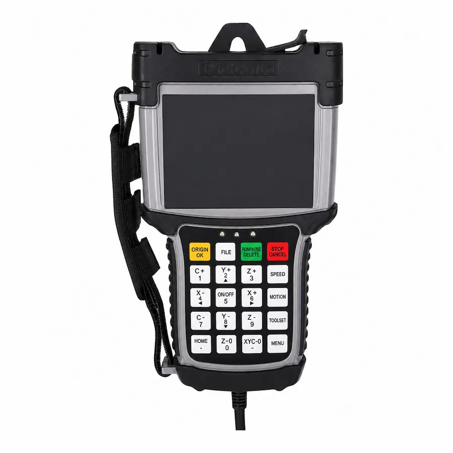
RichAuto B51 handheld front panel and color display. Reference photo; confirm the supplied controller and interface-board revision.
B5X SERIES · RA-B51
Three-axis color-screen DSP control for routing and engraving with machining-path preview and a matched machine interface.
Series: Browse the B5X controller range
CINKR supplies new, genuine RichAuto controllers and supports single-unit replacement orders. Eligible faults are covered by a one-year warranty. Most orders are dispatched within three working days after payment.
The supplied components, configuration, shipping cost and delivery estimate are confirmed in your quotation. Delivery, warranty and return terms.
PRODUCT GUIDE
Three-axis B5X DSP control featuring 5-inch color display, dynamic graphical toolpath preview, industrial TCP/IP networking and 4.0 MHz pulse generation.
QUICK DECISION
BEST FIT
CHECK BEFORE ORDERING
CONSIDER ANOTHER MODEL IF
The RichAuto B51 represents the flagship B5X motion control architecture engineered for high-precision three-axis CNC machining centers, heavy-duty production routers, and precision mold engraving equipment. Designed to meet the demanding requirements of modern production facilities, the B51 combines an expansive 5-inch color graphical LCD display, high-speed 4.0 MHz differential pulse generation, and integrated industrial TCP/IP Ethernet networking.
By executing toolpath simulation and dynamic trajectory optimization directly on a high-speed DSP processor, the B51 provides operators with visual confirmation of cutting toolpaths prior to cutting. This graphical preview capability virtually eliminates costly component scrap caused by improper coordinate zeroing or incorrect CAM post-processor selections. Machine builders and retrofitters can request a B51 quote configured for their exact drive specifications.
High-end production machines display model tags including B51, B51E, B51S, or B51C depending on target distribution channels:
| Model Marking | Keypad Faceplate Language |
|---|---|
| B51 | Base 5-inch color B5X platform |
| B51E | English-only keypad faceplate (Export standard) |
| B51S | Bilingual (Chinese + English) keypad faceplate |
| B51C | Bilingual (Chinese + English) keypad faceplate |
All 5-inch color graphical toolpath simulation capabilities, 4.0 MHz pulse outputs, TCP/IP networking, and firmware features are identical across B51, B51E, B51S, and B51C. The only difference is the button faceplate language. On-screen menus can be operated in complete English regardless of whether button caps are English-only or bilingual. Verify your breakout board model code, then request a B51 quotation.
Each standard RichAuto B51 control package arrives complete with industrial components intended for electrical cabinet mounting:
Inspect all terminal blocks and cable strain relief boots upon receipt to ensure physical integrity before cabinet mounting.
The 5-inch color display of the B51 elevates machine floor productivity and setup accuracy:
This graphical interface significantly shortens job changeovers on high-mix, custom fabrication equipment. To configure a system for your machine travel and driver interfaces, request an engineering quote.
Engineering documentation identifies two primary interface board revisions across the B51 family:
| Terminal Group | Terminal Identification | Connected Signal | Electrical Specification |
|---|---|---|---|
| Logic Power | 24V+, GND | Primary board power supply | 24V DC regulated, 2A isolated supply |
| Axis Differential | PUL+, PUL-, DIR+, DIR- (X, Y, Z) | High-speed step and direction lines | 5V RS-422 differential, 4.0 MHz max |
| Digital Inputs (1-16) | IN01 through IN16 | Limits, home sensors, tool touch plate | Optically isolated 24V NPN sinking inputs |
| Digital Outputs (1-16) | OUT01 through OUT16 | Spindle run, multi-speed, coolant | 24V open-collector transistor outputs |
| Handwheel Port | MPG Interface Terminals | Manual pulse generator connection | 5V differential encoder inputs |
Always inspect the board silkscreen revision code before rewiring field connections.
Integrating the B51 into facility local area networks streamlines manufacturing workflows:
Ensuring dedicated shielded CAT5e or CAT6 Ethernet cabling inside cabinet wire ducts preserves high signal-to-noise ratios.
Connecting the B51 to plant local area networks requires adhering to robust industrial communication practices:
Network segregation preserves high transmission speeds and guarantees that network broadcast storms cannot disrupt machine toolpath execution.
Diagnostic messages displayed on the 5-inch color screen assist technicians in isolating electrical and mechanical faults:
| Screen Diagnostic | Underlying Machine Condition | Inspection Procedure |
|---|---|---|
| Servo Drive Error (X/Y/Z) | Axis servo drive signaled an internal alarm or trip | Inspect servo drive front-panel error code; check motor power wiring |
| Travel Boundary Limit | Programmed toolpath exceeds configured soft limit boundaries | Verify workpiece zero coordinate setting; check G54 offset registers |
| Ethernet Link Down | Network cable disconnected or invalid IP configuration | Inspect RJ45 cable link LED; check controller subnet settings |
| Emergency Stop Input | Safety circuit opened or E-stop button engaged | Verify 24V continuity across emergency stop switches |
| Memory Capacity Reached | Internal program buffer full | Clear obsolete NC routines via the file storage utility menu |
Reviewing servo drive alarm registers and safety circuit continuity resolves the majority of commissioning interruptions.
When replacing an older controller with the advanced B51 system:
Our technical support desk can evaluate your electrical schematics and provide a verified replacement proposal.
To select the ideal platform across the RichAuto family:
SELECTION CHECKLIST
SPECIFICATIONS
Compare the current B5X platform below. For an existing machine, match the controller label, interface board and software version; reference documents and photos may show earlier hardware.
| Product model | B51 |
|---|---|
| Series | B5X |
| CPU | DSP |
| Internal memory | Ask CINKR for the memory capacity of the supplied controller. |
| Display | 5-inch |
| Communication | USB / TCP/IP |
| Controlled axes | 3 axes — Match the supplied hardware and software version. |
| Control signal | Differential |
| Drive system | Stepper / Servo — Match the supplied hardware and software version. |
| Inputs | 16 inputs |
| Outputs | 16 outputs |
| Additional I/O | Confirm the board variant and available terminals for additional I/O. |
| Minimum input unit | 0.001 mm |
| Max. pulse frequency | 4 MHz |
| Power supply | 24V DC — Interface-board input; check its rating separately from the handle supply. |
| Interpolation | Line / Arc / Curve — Match the supplied hardware and software version. |
| Breakpoint resume | Supported — Match the supplied hardware and software version. |
| Power-failure recovery | Supported — Match the supplied hardware and software version. |
| Soft / hard limit | Supported — Match the supplied hardware and software version. |
| Password protection | Supported — Match the supplied hardware and software version. |
| Rotary axis | Not supported |
| ATC support | Not supported |
| Multi-spindle / cylinders | Not supported |
| Plasma control | Not supported |
| Handwheel / MPG | Supported |
| Network communication | Supported — Match the supplied network interface and transfer workflow. |
COMPARE RELATED CONTROLLERS
Compare current platform applications, axes, display and I/O. Match the supplied board before replacement; earlier hardware may differ.
| Model | Main use | Axes | Display | I/O | Relationship |
|---|---|---|---|---|---|
| B51 | Three-axis routing with color preview | 3-axis | 5-inch | 16 inputs / 16 outputs | Selected model |
| B11 | Three-axis routing and engraving | 3-axis | 4.3-inch | 16 inputs / 16 outputs | Same-class option — compare functions, wiring and signals. |
| B57 | Three-axis automatic tool changing | 3-axis | 5-inch | 16 inputs / 16 outputs | Different platform — not a direct replacement. Machine-level compatibility check required. |
| B58 | Four-axis rotary machining with color preview | 4-axis | 5-inch | 16 inputs / 16 outputs | Different platform — not a direct replacement. Machine-level compatibility check required. |
B51 alternatives depend on the required motion and machine functions. A related model is not a promise of interchangeable wiring or firmware.
DOWNLOADS
Download reference documents below. Match the controller and interface-board revision before using any wiring instructions. For a replacement or new order, request the documents for the exact supplied hardware from CINKR.
Reference instructions and parameter guidance, mainly in English with some Chinese labels. These reference editions may describe earlier hardware; the supplied unit must match the document.
Free direct downloadReference wiring diagrams with English labels and signal notation. Confirm the matching board revision before using them.
Request the matching files for your hardware revision.Reference wiring diagrams with English labels and signal notation. Confirm the matching board revision before using them.
Request the matching files for your hardware revision.FAQ
The B51 upgrades to a larger 5-inch color LCD screen with dynamic graphical toolpath simulation, a faster processor delivering up to 4.0 MHz pulse output, standard TCP/IP Ethernet networking for file transfers, and dual-board wiring variants supporting both stepper and hybrid servo drives.
Yes. The B51 operating software includes full graphical toolpath preview, allowing operators to visually inspect cutting contours, check program boundaries, and verify coordinate zeroing on the 5-inch screen before engaging the spindle.
Documentation identifies B51E and B51E_1 interface board revisions. The B51E_1 revision incorporates dedicated differential driver connectors and modified auxiliary power isolation channels. Always match the exact board silkscreen when replacing assemblies.
Yes. The B51 interface board provides dedicated terminals for connecting manual pulse generator handwheels, enabling fine axis positioning during component alignment.
Yes. When the on-screen system language is toggled to English, all dynamic toolpath simulation, parameter menus, and coordinate readouts render in complete English.
B51E provides standard screw terminal blocks for stepper drives, while B51E_1 features multi-pin connectors and dedicated alarm channels designed for industrial AC servos.
Yes. All B51 models incorporate standard TCP/IP Ethernet ports supporting direct file loading from office design workstations across local subnets.
REQUEST A QUOTE
Tell us the quantity and destination country. For a replacement or upgrade, include any available machine details below. This form only prepares your message; nothing is submitted or stored.