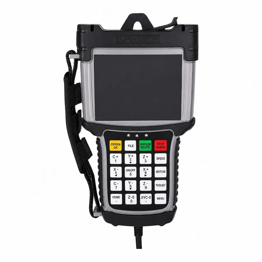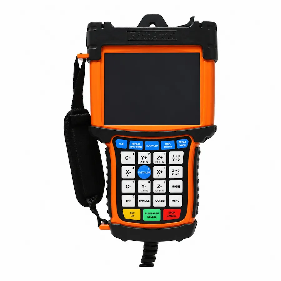
Choose the RichAuto B51 for a conventional three-axis router where an operator changes cutters. Choose the RichAuto B57 when the machine must control an automatic tool-changing sequence and already has, or is being built with, the corresponding spindle, tool storage and sensing hardware. The shared B5X color-screen platform is useful context, but the way the machine changes tools is the central distinction.
Several cutters in one machining job do not automatically mean that B57 is required. A router can run separate operations with deliberate manual changes. Conversely, purchasing a B57 does not supply the mechanical tool changer or establish a working sequence. This guide compares the two workflows so you can specify the controller as part of a complete machine requirement.
The numerical platform references below describe the current Chinese manufacturer specifications. Earlier English material and board manuals can differ; match the supplied controller and interface board before applying a value to an existing machine.
B51 vs B57: The Useful Comparison
Scroll horizontally to read all columns.
| Selection point | RichAuto B51 | RichAuto B57 |
|---|---|---|
| Main machine role | Standard routing and engraving | Routing with automatic tool changing |
| Controlled motion | Three-axis XYZ | Three-axis XYZ plus the supported ATC sequence |
| Tool change | Managed by the operator and job workflow | Managed through the configured machine sequence |
| Operating display | 5-inch color screen | 5-inch color screen |
| Current family I/O baseline | 16 inputs and 16 outputs | 16 inputs and 16 outputs |
| Current family pulse-frequency baseline | 4 MHz | 4 MHz |
| First machine check | Standard motion and auxiliary connections | Spindle, magazine, sensing and tool-change arrangement |
The B5X family information describes the display and control platform, including B57’s three-axis ATC role. Compare the supplied configuration on the B51 product page and B57 product page. On an installed machine, identify the board and parameters rather than assuming that a family specification describes every previous version.
The number of I/O connections also needs interpretation. A count of available ports does not prove that the required sensors and actuators can be assigned, connected and controlled in the intended sequence. List their functions and electrical requirements before treating the port count as sufficient.
How a Manual Tool-Change Job Works
A manual workflow divides the job into operations that the operator can manage. For example, a sign-making job might use one cutter for a pocket and another for the final profile. The first program ends or reaches a planned stopping point; the operator changes the cutter, establishes the correct tool reference and runs the next operation using the same work origin.
The controller choice must support the machine’s motion and file workflow, while the machining plan handles the interruption. The operator needs an unambiguous way to identify the next cutter, retain the work position and verify Z clearance. The CAM output should match this arrangement rather than issuing an automatic tool-change command that the machine cannot perform.
Manual changes can suit short runs, occasional cutter changes or a machine whose spindle and cabinet are already configured for that workflow. Their trade-off is operator involvement. Whether that is acceptable depends on the job mix, setup discipline and production schedule, not simply on how many tools appear in a CAM project.
What Automatic Tool Changing Adds
An ATC workflow must coordinate several events around the XYZ machining moves. The machine needs to approach a tool location, release or collect the correct holder, verify the necessary states and return to machining with the appropriate tool reference. The order depends on the installed tool-changing mechanism.
The B57 is the relevant controller in this comparison when that sequence is required. Its capability must be matched to the actual tool storage and machine arrangement. Record whether the tools sit in a fixed rack, a moving mechanism or another supported configuration. Provide the builder’s sequence and signal requirements rather than relying on a photograph of the spindle alone.
A controller can command an action only within the configured machine system. Tool retention, magazine position and other required conditions must be represented by the correct hardware and signals. A command that completes on the display is not proof that the holder has physically engaged. Commissioning should verify the actual sequence and its response when an expected condition is missing.
Check These Machine Requirements Before Selecting B57
Spindle and Tool Holders
Identify the spindle’s tool-release mechanism and the holder type. A conventional manually tightened collet spindle does not become an automatic tool-changing spindle through a new controller. The mechanical interface, release action and tool-retention checks must suit automatic operation.
Record the required utilities and the machine builder’s operating conditions. Where pneumatics are used, the release and retention arrangement needs the specified air supply and valves. Obtain those requirements from the equipment documentation instead of applying a pressure value from a different machine.
Magazine, Sensors and Auxiliary Movements
Describe each tool position and any movement needed to present it. Include covers, lifts or dust-hood actions where they interact with tool changing. A practical sequence must prevent these devices from conflicting with the spindle or the travel path.
List every required input and output by function, including the expected state for each stage. The review should cover what the controller commands, what the sensors report and what happens if a transition is not completed. Port labels, signal polarity and timing belong in that machine-specific review.
Tool References and CAM Output
The correct physical tool also needs the correct machining reference. Define how each tool’s length is established and how the machine identifies it. Consistent holder numbering, magazine positions and CAM tool numbers prevent a correct movement sequence from selecting the wrong cutter.
The post processor must produce commands compatible with the commissioned B57 arrangement. A generic program that runs on a manually changed three-axis router does not establish ATC suitability. Review tool-change commands, spindle behavior, retracts and coordinate handling before using a multi-tool job.
Can a B51 Router Be Converted to B57?
Start by determining whether the router can support an ATC conversion mechanically and electrically. If it already has a suitable spindle and tool storage but needs controller work, the investigation is different from converting a basic single-collet router. The latter may require a spindle, holders, magazine, pneumatic equipment, sensing, cabinet changes and revised machine setup.
Use this conversion review:
- Identify the present spindle and decide whether it supports automatic tool release and retention.
- Document where tools will be stored and how the spindle reaches each location.
- Map the required sensors, actuators and interlocks against the proposed board and sequence.
- Define tool numbering, measurement and CAM output for the intended workflow.
- Scope controller supply, mechanical work, wiring, parameters and commissioning together.
Retain the existing motion settings and wiring records before conversion. They help describe the starting machine, but copying them unchanged does not complete the new tool-changing setup. The final arrangement needs checks for tool locations, clearances, sequence states and recovery behavior as well as ordinary axis movement.
Which Workflow Fits Your Production?
Scroll horizontally to read all columns.
| Your situation | Direction to investigate | Decision to make |
|---|---|---|
| Occasional jobs with one or two cutters | B51 with a planned manual workflow | Is operator attendance acceptable? |
| Repeated multi-tool programs on an ATC-equipped router | B57 | Does the controller fit the installed tool-changing system? |
| Basic router being considered for an ATC retrofit | Complete conversion review | Are hardware work and commissioning justified? |
| Color display is desired, but tool changes stay manual | B51 | Does the machine need any B57-specific function? |
| A rotary axis is required | Separate four-axis selection | What motion must the additional axis perform? |
Estimate the value of ATC using the real job sequence: number of changes, operator availability, setup effort and repeat work. Do not assume a fixed time saving or payback from a controller specification. A well-organized manual process can be adequate for one workshop, while another needs automatic changes to run its normal production.
Prepare a Complete Selection Request
For a B51 request, describe the three-axis router, drives, spindle controls, board and desired file-transfer workflow. For B57, add the spindle release arrangement, holder type, tool storage, required sensors and the machine builder’s sequence. Photos should show labels and terminals clearly enough to relate them to the wiring information.
The B57 ordering guide expands the machine information to collect once ATC is the right direction. If your decision is mainly about the handheld interface and ordinary routing rather than automatic changes, read B11 vs B51. These are different comparisons: first choose the required machine function, then compare the operating interface within that scope.