


BEST FIT
Choose A11 if:
- Your machine uses conventional X, Y and Z motion.
- An offline handheld workflow meets your operating needs.
- The matching A1X board suits the machine interface.
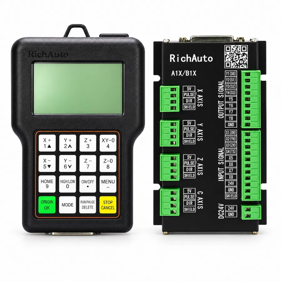
RichAuto A11 handheld controller and interface board. Reference photo; confirm the supplied controller and interface-board revision.
A1X SERIES · RA-A11
Offline three-axis DSP control for CNC routing and engraving, with matching handle and interface-board checks for replacement orders.
Series: Browse the A1X controller range
CINKR supplies new, genuine RichAuto controllers and supports single-unit replacement orders. Eligible faults are covered by a one-year warranty. Most orders are dispatched within three working days after payment.
The supplied components, configuration, shipping cost and delivery estimate are confirmed in your quotation. Delivery, warranty and return terms.
PRODUCT GUIDE
Three-axis handheld DSP control for routing and engraving, also listed as A11E or A11S; verify the suffix, handle, interface board and replacement wiring.
QUICK DECISION
BEST FIT
CHECK BEFORE ORDERING
CONSIDER ANOTHER MODEL IF
The RichAuto A11 is an industrial standalone DSP motion controller engineered specifically for three-axis CNC woodworking routers, engraving equipment, and stone milling machinery. By executing toolpath interpolation directly on a dedicated high-speed processor, the A11 eliminates the instability, operating system latency, and electromagnetic vulnerabilities associated with general-purpose office computers on factory floors.
Operators control machine movements, zero work coordinates, adjust feed overrides, and execute cutting routines via an ergonomic handheld pendant. Program execution proceeds without continuous PC tethering, providing reliable daily performance in high-dust and electrically noisy production environments. Before placing a new procurement request or replacing an existing installation, review machine kinematics and cabinet interface details to ensure complete operational alignment.
Machine nameplates, industrial equipment listings, and machine builder documentation frequently present varying model designations such as A11, A11E, A11S, or A11C. In industrial workshop environments, these model codes identify faceplate button language formats:
| Model Marking | Keypad Faceplate Language |
|---|---|
| A11 | Base 3-axis controller designation |
| A11E | English-only keypad faceplate (Export standard) |
| A11S | Bilingual (Chinese + English) keypad faceplate |
| A11C | Bilingual (Chinese + English) keypad faceplate |
All internal motion control processing, 50-pin interface board connections, pulse output frequencies, and firmware algorithms are identical across A11, A11E, A11S, and A11C. The only distinction is the silkscreen language on the physical keypad buttons. When preparing an equipment retrofit, check your operator language preference, then request an A11 quote with your machine specifications.
Standard delivery packages for the RichAuto A11 three-axis control system include four core components designed for complete electrical cabinet integration:
Examine all package elements upon receipt. Damaged shielding on the 50-pin cable or stripped screw terminals on the breakout board compromise electrical noise immunity.
The RichAuto A11 platform operates across two separate electrical domains that must remain isolated during cabinet integration:
If your electrical cabinet supplies 5V auxiliary logic directly to machine sensors rather than standard 24V industrial proximity switches, sensor signal conditioning modules must be verified prior to connection.
Field wiring between the cutting machine and the RichAuto A11 terminates at the DIN-rail interface breakout board. The board groups terminal connections logically to prevent interference between low-voltage logic and inductive field devices:
| Terminal Group | Terminal Identifiers | Signal Functions | Installation Checkpoint |
|---|---|---|---|
| Main Power | 24V+, GND | 24V DC input power for board logic and inputs | Observe polarity; supply clean regulated switching DC |
| Axis Step / Direction | X-PUL, X-DIR, Y-PUL, Y-DIR, Z-PUL, Z-DIR | Common-anode step and direction outputs for axes | Connect drive OPTO/PUL+ to +5V; connect PUL- to X-PUL |
| Limit & Home Inputs | X-, Y-, Z-, X0, Y0, Z0 | Mechanical switch or NPN proximity sensor inputs | Verify NPN normally-open switch configuration |
| Spindle Control | S0, S1, S2, GND (Terminal J7) | Multi-step discrete spindle speed selection | Connect to inverter multi-speed digital input terminals |
| Tool Setting | Cutter / Tool Sensor | Contact touch plate input for automated tool setting | Ground probe clip to spindle; signal to touch plate |
The 50-pin interconnect cable carries both the regulated 5V power bus and sensitive high-speed digital pulse trains. Route this cable through dedicated low-voltage wire trays separated by at least 150 mm from high-voltage AC spindle inverter output lines.
The RichAuto A11 reads standard numerical control programs compiled in industry-standard G-code or HPGL formats. Machining files are transferred to the machine using standard USB flash drives:
.nc, .tap, or .gcode extensions. Avoid special characters, spaces, or non-ASCII symbols in directory and program names.To establish smooth workflow integration, review post-processor output settings in your CAM software to ensure arc interpolation (G02/G03) and feedrate words correspond with A11 syntax.
When the A11 controller detects abnormal hardware conditions, invalid coordinate transformations, or toolpath limits, diagnostic messages appear on the monochrome display. Review these initial checks before replacing components:
| Display Message | Probable Root Cause | Corrective Action |
|---|---|---|
| Limit Overrun (X+/X-/Y+/Y-/Z+/Z-) | Axis position exceeded soft limits or triggered home sensor | Switch to manual jog mode; hold Cancel while jogging axis away from sensor |
| File Read Error / No File | Incompatible USB drive format or corrupted G-code file | Reformat USB drive to FAT32; verify file ends with standard program terminators |
| Spindle Fault / Not Ready | Inverter fault contact open or spindle enable circuit unpowered | Check 24V supply to inverter run relay; examine inverter error code |
| Step Loss Warning / Pulse Error | Acceleration set higher than motor torque capacity | Reduce maximum axis acceleration parameters in the machine setup menu |
| Memory Full | Internal 512 MB flash capacity reached | Delete obsolete cached G-code files using the file management menu |
For comprehensive diagnostic sequences covering persistent boot failures or display power issues, refer to our diagnostic guides before ordering replacement assemblies.
When requesting a replacement A11 controller for an operational machine or an out-of-warranty rebuild, collect the following technical items from your equipment:
Submit these details through our A11 quotation request form to verify exact hardware compatibility before shipment.
While the RichAuto A11 serves as an industry standard for straightforward three-axis routers, certain machine configurations warrant step-up models:
For additional guidance on multi-axis equipment retrofits or spindle inverter communication, submit your machine details for an engineering review and quote.
SELECTION CHECKLIST
SPECIFICATIONS
Compare the current A1X platform below. For an existing machine, match the controller label, interface board and software version; reference documents and photos may show earlier hardware.
| Product model | A11 |
|---|---|
| Series | A1X |
| CPU | DSP |
| Internal memory | 512 MB |
| Display | 3-inch |
| Communication | USB flash drive / USB cable — Match the supplied hardware and software version. |
| Controlled axes | 3 axes |
| Control signal | Common-anode |
| Drive system | Stepper / Servo — Match the supplied hardware and software version. |
| Inputs | 8 inputs |
| Outputs | 8 outputs |
| Additional I/O | Confirm the board variant and available terminals for additional I/O. |
| Minimum input unit | 0.001 mm |
| Max. pulse frequency | 1 MHz |
| Power supply | 24V DC — Interface-board input; check its rating separately from the handle supply. |
| Interpolation | Line / Arc / Curve — Match the supplied hardware and software version. |
| Breakpoint resume | Supported — Match the supplied hardware and software version. |
| Power-failure recovery | Supported — Match the supplied hardware and software version. |
| Soft / hard limit | Supported — Match the supplied hardware and software version. |
| Password protection | Supported — Match the supplied hardware and software version. |
| Rotary axis | Not supported |
| ATC support | Not supported |
| Multi-spindle / cylinders | Not supported |
| Plasma control | Not supported |
| Handwheel / MPG | Not supported — Match the supplied hardware and software version. |
| Network communication | Not supported — Match the supplied hardware and software version. |
COMPARE RELATED CONTROLLERS
Compare current platform applications, axes, display and I/O. Match the supplied board before replacement; earlier hardware may differ.
| Model | Main use | Axes | Display | I/O | Relationship |
|---|---|---|---|---|---|
| A11 | Three-axis routing and engraving | 3-axis | 3-inch | 8 inputs / 8 outputs | Selected model |
| B11 | Three-axis routing and engraving | 3-axis | 4.3-inch | 16 inputs / 16 outputs | Same-class option — compare functions, wiring and signals. |
| B51 | Three-axis routing with color preview | 3-axis | 5-inch | 16 inputs / 16 outputs | Same-class option — compare functions, wiring and signals. |
A11 alternatives depend on the required motion and machine functions. A related model is not a promise of interchangeable wiring or firmware.
DOWNLOADS
Download reference documents below. Match the controller and interface-board revision before using any wiring instructions. For a replacement or new order, request the documents for the exact supplied hardware from CINKR.
Reference instructions and parameter guidance, mainly in English with some Chinese labels. These reference editions may describe earlier hardware; the supplied unit must match the document.
Free direct downloadFirmware packages must match the exact model, hardware revision and current version.
Request the matching files for your hardware revision.FAQ
The A11E is the English-interface designation of the standard A11 controller platform. Both versions share the identical internal processing architecture, three-axis motion kernel, and terminal pinouts. The letter E indicates English silkscreen legends on the keypad faceplate and default English menu firmware rather than a change in physical axis capacity.
Suffix markings such as A11S or A11C designate internal hardware revisions or specific factory-bundled parameter sets within the A11 family. They do not alter the fundamental common-anode signal topology or 50-pin ribbon connector layout, but cabinet builders must verify interface board supply voltages and terminal silkscreens before powering the system.
Inspect the intermediate interface breakout board mounted on the DIN rail inside your electrical cabinet. Terminal blocks labeled DC 24V supply the optocoupler isolation circuits, while the handheld pendant processor receives regulated 5V via the shielded 50-pin interconnect cable. Never connect 24V shop power directly to the handheld pendant cable.
Yes. The A11 reads standard G-code files from FAT16 or FAT32 formatted USB thumb drives up to 32 GB. Program files can be executed directly from the drive or copied into the 512 MB internal flash memory for standalone operation without a connected storage device.
Photograph the rating label on the rear enclosure of the handheld pendant, the silkscreen model code on the DIN-rail interface board, and the existing driver step/direction wiring blocks. Submit these details through the CINKR quote form to ensure matching board revisions.
The letter E designates an English-only keypad faceplate and default English menu firmware. Both A11 and A11E share the identical 3-axis digital signal processing core, 50-pin ribbon cable pinout, and common-anode driver outputs.
A11S and A11C indicate bilingual keypad faceplates featuring both Chinese and English button legends. S and C represent different production batches but maintain identical 3-axis wiring and terminal interfaces.
Yes. Because A11E, A11S, and A11C share the exact same terminal board connections and 24V auxiliary power specifications, they are interchangeable provided existing motor pulse parameters are preserved.
REQUEST A QUOTE
Tell us the quantity and destination country. For a replacement or upgrade, include any available machine details below. This form only prepares your message; nothing is submitted or stored.