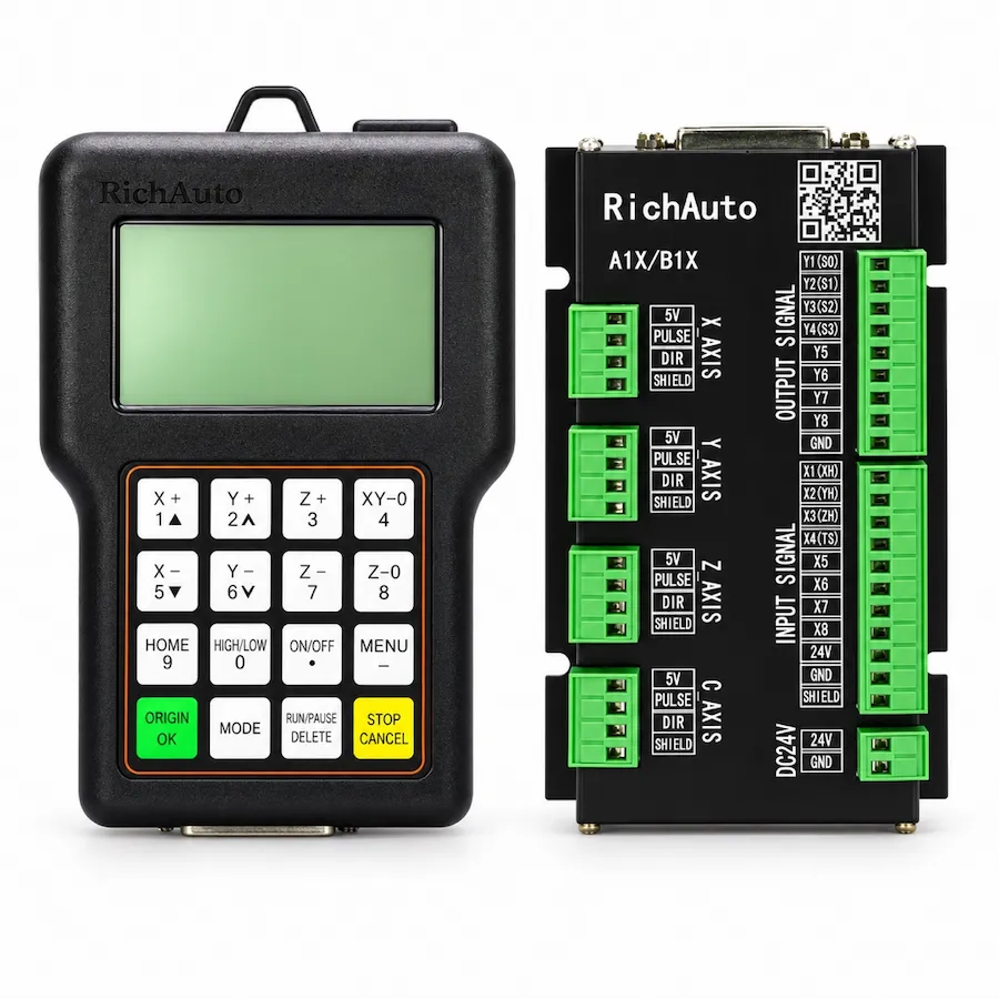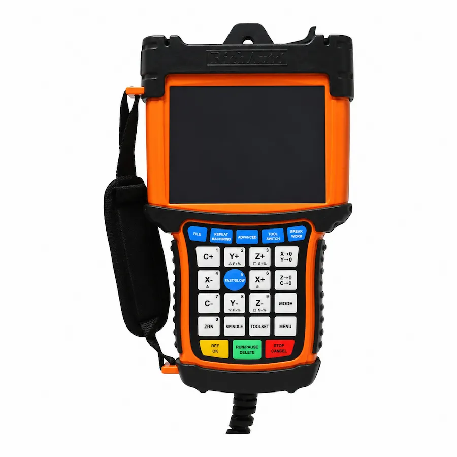
A controller that is not working can mean five different failures: no power, no display, no motion, no spindle or no file. Each has its own evidence and its own first check. Replacing the controller before identifying the layer is the most expensive way to troubleshoot, because a new unit installed into an existing fault behaves exactly like the old one.
This page is a triage path, not a repair manual. It tells you which layer to test, what to record, and which detailed guide covers that layer. Stop at the point where the evidence identifies the controller itself, and record everything before ordering.
Start With One Question: Does the Display Respond?
The display separates two families of fault immediately. If the display is completely inactive, work on the supply and the connection. If the display responds but the machine does not behave, work on the function that failed.
Scroll horizontally to read all columns.
| What you observe | First evidence to collect | Where to continue |
|---|---|---|
| No display, no reaction | Board input voltage at the terminal, fuse state, earth path | Blank-screen checks |
| Display on, no axis motion | Drive enable, emergency-stop circuit, signal common | Motion checks below |
| Axis moves the wrong distance or direction | Parameters against the recorded values, mechanical binding | Parameter and reference checks |
| Spindle will not start or change speed | Spindle command type, drive status, control cable | Spindle troubleshooting |
| Program will not load or stops partway | File, media, transfer path, program size | File-handling checks |
| Alarm appears during motion | Alarm text, axis, position, what happened immediately before | Input and limit checks |
Collect the evidence in the right-hand column before moving to the next layer. A photograph of the display at the moment of failure is worth more than a description written an hour later.
When the Display Is Inactive
Treat a dark display as a supply question first. Confirm the voltage at the board input terminal, inspect the protective earth and check the fuse arrangement that feeds the control circuit. If the supply is present at the terminal but the controller shows nothing, the evidence is beginning to point at the controller.
Two cautions apply. Do not move a supply from another machine onto the controller to “test” it, because the rating may differ. Do not open the handle to reseat internal connections unless that step is described for your hardware; the blank-screen guide sets out the checks that do not require opening the unit.
A display that flickers or shows an incomplete screen is a different case from one that never lights. Record which it is, because intermittent behaviour changes the diagnosis.
When the Display Works but Motion Does Not
Motion requires three things at once: a command, an enabled drive and a valid signal path. Any of the three failing produces the same visible result.
- Confirm the machine is not held in emergency stop, and that the stop circuit has been reset deliberately.
- Confirm the drives are enabled and not reporting a fault of their own.
- Confirm the signal common is shared between controller and drive.
- Confirm the axis is not held by a mechanical or software limit.
- Confirm the commanded distance and the displayed position change together.
If the display shows the position changing while the machine does not move, the fault sits between the controller output and the drive. If the display shows no position change, the controller is not issuing motion, and the cause is upstream: mode, program, limit or enable state.
When the Machine Moves but the Result Is Wrong
Wrong distance, wrong direction or a lost work origin is usually a parameter or reference problem rather than a failed controller. Compare the current values with the record kept for the machine, and check the mechanical arrangement before changing a value.
Three questions narrow it quickly. Did the behaviour change after a parameter edit, a firmware change or a mechanical repair? Is the error proportional to the commanded distance or fixed? Does it appear on one axis or on all axes? The answers distinguish a scale error, a reference error and a mechanical fault.
The homing and work-zero guide covers the reference sequence and the tool-setting checks that follow it.
When the Spindle Is the Only Fault
A spindle that will not start, will not change speed or runs at the wrong speed involves the controller output, the drive and the machine wiring. Confirm the command type expected by the drive and the actual signal at the control terminals.
If the spindle runs from the drive’s own panel but not from the controller, the fault is in the command path. If it does not run from either, start with the drive and its supply. The spindle troubleshooting guide sets out that sequence, including the checks that should be done with the spindle disconnected from the work.
When the Fault Is Really a File
A program that will not load, a drive that is not recognised or a job that stops partway can look like a controller failure. Check the file on a computer first: open it, confirm the format and size, and confirm the media is readable elsewhere.
The USB and file-reading guide covers media preparation and the file checks that precede any controller test. This is worth doing before touching the wiring, because a file fault reproduces exactly like a motion fault.
Stop Conditions: When to Replace
Replace the controller when the evidence points at the controller and the reversible steps have been tried with the parameters recorded.
Scroll horizontally to read all columns.
| Condition | Supporting evidence | Before ordering |
|---|---|---|
| No display with a confirmed supply | Voltage present at the board input, earth checked | Photograph label and board |
| Inputs respond but outputs do not | Input state changes on display, no output at terminals | Confirm drive and common |
| Controller will not start after a matched reset | Reset performed with parameters recorded | Keep the parameter record |
| Repeated failure after a correct installation | Same fault on a matched replacement | Review supply and wiring first |
Before ordering, record the label, the board marking, the current version and the parameter values. Those four items decide whether the replacement will fit, and they are the first questions any supplier will ask. The replacement checklist covers the wiring evidence to photograph.
What Not to Do
- Do not swap boards between machines to test them, because an incompatible board can damage the controller or the drive.
- Do not reset repeatedly in the hope that the fault clears; each reset can erase evidence and parameters.
- Do not apply a supply voltage from a different machine to prove the controller works.
- Do not order a replacement before recording the parameters, even when the fault seems obvious.
- Do not treat an alarm as a single fault; record the axis, position and preceding action.
A final caution concerns repetition. Repeating the same test and expecting a different result is common during a breakdown, because each repetition feels like progress. It is not. If a check has been done correctly and the result is unchanged, move to the next layer instead of repeating the check.
Keep the notes short but dated. A timeline of what changed, what was tested and what was observed is what allows a second person to help without starting again.
A controlled sequence costs an hour and usually narrows the fault to one layer. An unordered sequence of parts often costs a week and leaves the original fault in place.