
BEST FIT
Choose B57 if:
- The router needs automatic tool changing with three-axis motion.
- The tool rack, spindle and change sequence can be matched.
- The supplied B5X interface fits the required ATC signals.

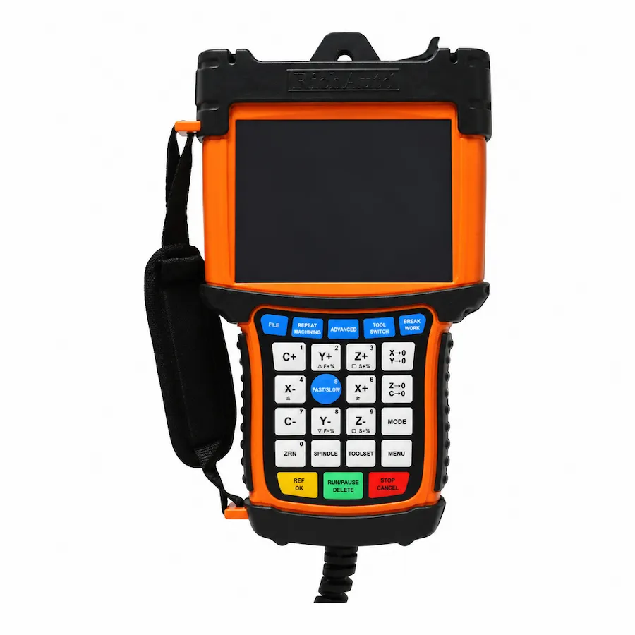
RichAuto B57 handheld front panel and color display. Reference photo; confirm the supplied controller and interface-board revision.
B5X SERIES · RA-B57
Three-axis DSP control for ATC CNC routers with tool-rack or magazine functions and a color-screen operating interface.
Series: Browse the B5X controller range
CINKR supplies new, genuine RichAuto controllers and supports single-unit replacement orders. Eligible faults are covered by a one-year warranty. Most orders are dispatched within three working days after payment.
The supplied components, configuration, shipping cost and delivery estimate are confirmed in your quotation. Delivery, warranty and return terms.
PRODUCT GUIDE
ATC control for tool-magazine routers, also listed as B57E; confirm the rack layout, terminal map and board version before ordering.
QUICK DECISION
BEST FIT
CHECK BEFORE ORDERING
CONSIDER ANOTHER MODEL IF
The RichAuto B57 is an industrial standalone DSP motion controller engineered specifically for CNC routers equipped with automatic tool changers (ATC). Operating on the powerful B5X hardware platform, the B57 manages the complete tool change cycle for single-spindle machines utilizing pneumatic drawbars and toolholder magazines (such as ISO30, BT30, or HSK63F taper systems).
During an automated tool change, the B57 coordinates spindle deceleration, pneumatic dust hood retraction, axis travel to the designated pocket, toolholder unclamping with taper air purge, tool pickup, clamp sensor verification, and automated tool length touch-off. The 5-inch color LCD display provides operators with dynamic toolpath simulation and clear tool magazine status readouts. Machine builders and facilities can request a B57 quote configured for their exact magazine kinematics.
In procurement channels and machine documentation, the controller appears under designations such as B57, B57E, B57S, or B57C:
| Model Marking | Keypad Faceplate Language |
|---|---|
| B57 | Base ATC motion control platform |
| B57E | English-only keypad faceplate (Export standard) |
| B57S | Bilingual (Chinese + English) keypad faceplate |
| B57C | Bilingual (Chinese + English) keypad faceplate |
All automatic tool changer macro sequences, spindle drawbar safety interlocks, pneumatic air purge logic, and firmware are identical across B57, B57E, B57S, and B57C. The only distinction is the silkscreen language on the physical keypad buttons. Suffixes do not alter motion algorithms, tool change macros, or terminal pin assignments. When planning a machine purchase, submit an equipment inquiry.
Factory firmware packaging and engineering diagrams identify two distinct mechanical tool magazine arrangements supported by the B57:
Matching the firmware package to your machine physical layout ensures correct approach trajectories and prevents mechanical collisions during tool loading.
The B57 interface breakout board provides high-density optical isolation specifically organized for ATC safety interlocks:
| Terminal Identifier | Signal Function | Electrical Characteristic | Safety Interlock Purpose |
|---|---|---|---|
| X01, X02, X03 | X, Y, Z Axis Home Sensors | 24V NPN sinking inputs | Machine reference calibration |
| X04 | Tool Setting Touch Plate | 24V NPN input | Automated tool length measurement |
| X05 | Servo Drive Alarm Input | 24V isolated input | Immediate motion stop on servo trip |
| X06, X07 | Hard Limit, Emergency Stop | 24V safety loop inputs | Overtravel and safety circuit protection |
| X08 | Manual Foot Switch Input | 24V digital input | Manual tool release pedal |
| X09 | Main Pneumatic Pressure Sensor | 24V digital input | Inhibit tool change if air pressure < 0.6 MPa |
| X10 | Manual Tool Unclamp Button | 24V digital input | Operator button on spindle nose |
| X11, X12 | Spindle Inverter Fault / Stop | 24V digital inputs | Verify spindle completely stopped before unclamp |
| X13, X14 | Tool Clamped / Unclamped Reeds | 24V proximity inputs | Confirm drawbar position before axis motion |
| X15, X16 | Dust Hood Up / Tool in Pocket | 24V digital inputs | Dust hood position and pocket occupancy checks |
| Y01 | Spindle Forward Run (FWD1) | 24V open-collector relay | Spindle inverter run command |
| Y03, Y04 | Operation Lamp, Alarm Beacon | 24V transistor outputs | Visual machine status indicators |
| Y06 | Dust Hood Lift Cylinder | 24V solenoid valve output | Retract dust hood during tool changes |
| Y07 | Toolholder Cone Air Blow | 24V solenoid valve output | Blast compressed air to clean taper during change |
| Y08 | Tool Unclamp Solenoid Valve | 24V solenoid valve output | Actuate pneumatic cylinder to release toolholder |
Never bypass input terminals X13 and X14; verifying toolholder clamping prevents catastrophic spindle damage caused by running an unseated toolholder at high RPM.
Engineering documentation identifies two primary interface board models within the B57 family:
Inspect your cabinet interface card before ordering replacements to guarantee terminal alignment.
Connecting the ATC spindle and sensor network requires disciplined wiring practices:
Following these connection guidelines prevents transient electrical noise from disrupting high-speed motion interpolation. To inspect terminal schematics or verify ATC sequence logic, request a B57 engineering review.
Automated tool changers demand repeatable tool length compensation after every toolholder pickup:
Integrating automated tool measurement eliminates manual touch-off errors and protects expensive spoilboards from accidental gouging.
Diagnostic messages on the 5-inch color screen guide rapid troubleshooting during automated tool changes:
| Screen Diagnostic | Underlying Machine Condition | Corrective Procedure |
|---|---|---|
| Tool Unclamp Timeout | Tool release cylinder failed to actuate within programmed delay | Check shop air supply pressure; inspect solenoid valve and reed sensor X14 |
| Tool Clamped Sensor Lost | Toolholder clamp confirmation lost during spindle run | Immediately stop spindle; check drawbar spring tension and sensor X13 |
| Air Pressure Low Trip | System air pressure dropped below safe threshold (Input X09) | Verify compressor operation; inspect air regulator and main supply line |
| Tool Number Out of Range | Commanded tool number exceeds configured magazine pocket count | Verify G-code tool calls against configured magazine capacity |
| Spindle Stop Interlock | Tool release commanded while inverter run contact closed | Inspect inverter zero-speed output contact wiring to input X12 |
Maintaining dry, lubricated compressed air at stable 0.65 MPa pressure eliminates over 85% of automated tool change errors.
When requesting a replacement B57 controller or evaluating a machine retrofit:
Submit your machine specifications through our B57 quotation portal for a verified compatibility review.
SELECTION CHECKLIST
SPECIFICATIONS
Compare the current B5X platform below. For an existing machine, match the controller label, interface board and software version; reference documents and photos may show earlier hardware.
| Product model | B57 |
|---|---|
| Series | B5X |
| CPU | DSP |
| Internal memory | Ask CINKR for the memory capacity of the supplied controller. |
| Display | 5-inch |
| Communication | USB / TCP/IP |
| Controlled axes | 3 axes |
| Control signal | Differential |
| Drive system | Stepper / Servo — Match the supplied hardware and software version. |
| Inputs | 16 inputs |
| Outputs | 16 outputs |
| Additional I/O | Confirm the board variant and available terminals for additional I/O. |
| Minimum input unit | 0.001 mm |
| Max. pulse frequency | 4 MHz |
| Power supply | 24V DC — Interface-board input; check its rating separately from the handle supply. |
| Interpolation | Line / Arc / Curve — Match the supplied hardware and software version. |
| Breakpoint resume | Supported — Match the supplied hardware and software version. |
| Power-failure recovery | Supported — Match the supplied hardware and software version. |
| Soft / hard limit | Supported — Match the supplied hardware and software version. |
| Password protection | Supported — Match the supplied hardware and software version. |
| Rotary axis | Not supported |
| ATC support | Supported |
| Multi-spindle / cylinders | Not supported |
| Plasma control | Not supported |
| Handwheel / MPG | Supported |
| Network communication | Supported — Match the supplied network interface and transfer workflow. |
COMPARE RELATED CONTROLLERS
Compare current platform applications, axes, display and I/O. Match the supplied board before replacement; earlier hardware may differ.
| Model | Main use | Axes | Display | I/O | Relationship |
|---|---|---|---|---|---|
| B57 | Three-axis automatic tool changing | 3-axis | 5-inch | 16 inputs / 16 outputs | Selected model |
| B51 | Three-axis routing with color preview | 3-axis | 5-inch | 16 inputs / 16 outputs | Different platform — not a direct replacement. Machine-level compatibility check required. |
| B58 | Four-axis rotary machining with color preview | 4-axis | 5-inch | 16 inputs / 16 outputs | Different platform — not a direct replacement. Machine-level compatibility check required. |
B57 alternatives depend on the required motion and machine functions. A related model is not a promise of interchangeable wiring or firmware.
DOWNLOADS
Download reference documents below. Match the controller and interface-board revision before using any wiring instructions. For a replacement or new order, request the documents for the exact supplied hardware from CINKR.
Reference instructions and parameter guidance, mainly in English with some Chinese labels. These reference editions may describe earlier hardware; the supplied unit must match the document.
Free direct downloadReference wiring diagrams with English labels and signal notation. Confirm the matching board revision before using them.
Request the matching files for your hardware revision.Reference wiring diagrams with English labels and signal notation. Confirm the matching board revision before using them.
Request the matching files for your hardware revision.FAQ
The B57 supports both linear tool racks (gantry-mounted or table-end linear tool racks typically holding 6 to 12 tools) and rotary carousel tool magazines. It executes automated tool clamp/unclamp pneumatic cylinder sequencing, spindle dust hood retraction, and toolholder taper blow-off.
Manufacturer documentation and firmware packaging distinguish between Back Tool Rack (table-end fixed tool bar) and Side Tool Rack (gantry-side or carousel) layouts. Each configuration utilizes dedicated motion trajectories and sensor interlock timing during tool exchange cycles.
The B57E standard breakout board is engineered for stepper or hybrid servo drives, while the B57E_1 revision is specifically tailored for industrial AC servo drives with dedicated alarm feedback lines and high-current relay outputs.
Yes. The B57 integrates safety inputs monitoring toolholder clamped, toolholder unclamped, spindle stop confirmation, and pneumatic pressure thresholds before allowing tool exchange motion.
Yes. Both models execute the exact same automated tool change cycles, spindle stop interlocks, cone air purge blasts, and tool length sensor touch-offs.
Yes. Dedicated firmware packages exist for both fixed table-end racks (Back Rack) and traveling gantry-side racks (Side Rack) across all B57 variants.
Yes, when paired with the B57E_1 servo interface breakout board, which provides dedicated servo alarm inputs and high-current relay outputs.
REQUEST A QUOTE
Tell us the quantity and destination country. For a replacement or upgrade, include any available machine details below. This form only prepares your message; nothing is submitted or stored.