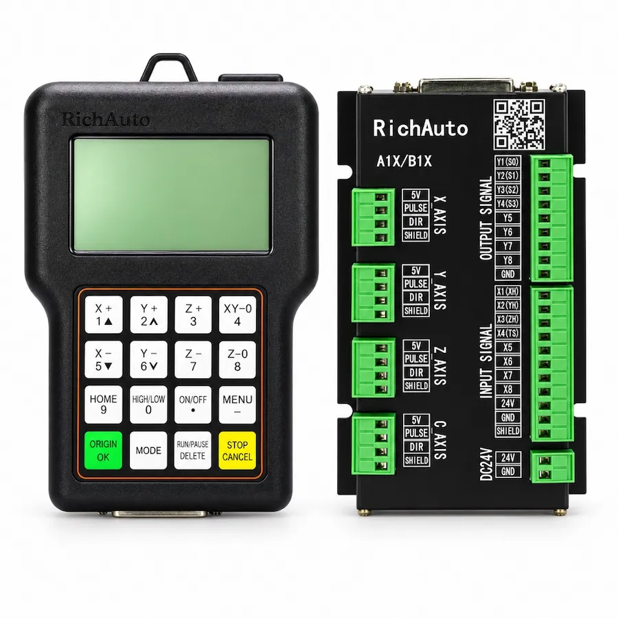
If a RichAuto A11 spindle will not start, first compare manual spindle control with program operation. If it starts but will not change speed, investigate the speed-selection path separately. XYZ movement, spindle start and spindle speed are different functions, so normal axis motion does not prove that the spindle command or reference is reaching the drive.
The diagnostic sequence below follows the command from the controller through the interface board to the spindle drive. It does not assign universal A11 terminal numbers, voltages or VFD parameters. Use the wiring and operating information for the installed controller, board and drive; observations at live electrical equipment belong to a qualified technician following the machine’s procedure.
Follow the Spindle Command Chain
- A11 requestManual action or an interpreted program instruction
- Interface boardThe installed start and speed connections
- Spindle driveCommand source, speed reference and operating state
- Spindle responseActual start, stop and speed behavior
A missing response can originate at different points in this chain. The controller may not request a start, the request may not reach the drive, or the drive may reject it because of an alarm or operating condition. A speed problem can occur even when the start command works correctly.
For the controller’s capabilities, see the A11 product page. The A1X family description identifies grade-based spindle control. On an existing machine, identify the actual board and spindle-control arrangement before applying that information to a particular terminal.
Record the Symptom Before Changing Settings
Scroll horizontally to read all columns.
| Observed behavior | First distinction to make |
|---|---|
| No start in manual or program operation | Does the drive receive a start request, and is it ready to run? |
| Manual start works, program start does not | Does the file request the intended action, and does the controller interpret it? |
| Drive keypad operation works, controller operation does not | Is the configured remote command path the intended one? |
| Spindle starts but runs at one speed | Is the speed reference fixed, local or correctly selected remotely? |
| Some speed selections work, others do not | Do the selected grades and corresponding signals agree? |
| An alarm appears after a start request | What does the exact drive or controller alarm mean? |
Record whether the problem began after wiring work, a new file, parameter changes or a controller replacement. Preserve photos of the original connections and parameter records. If several settings are changed before the first comparison, it becomes much harder to distinguish the original fault from a new configuration issue.
Check the Machine’s Operating State
Before investigating signals, record any emergency-stop, limit, drive or spindle alarm shown by the machine. A blocked operating state can prevent a start request from being acted on. Follow the machine’s procedure to identify the reason; do not bypass an interlock to make a test succeed.
Check what the spindle drive displays when the request is made through an approved operating test. A drive showing an alarm is a different case from one that remains ready but receives no run request. A displayed target frequency is also different from confirmed physical rotation.
An alarm code should be interpreted using the exact drive model’s documentation. The controller name does not determine the meaning of a VFD fault. If the fault involves power, motor connections or the spindle itself, changing an A11 program setting will not address that condition.
Compare Manual and Program Spindle Control
Use the machine’s documented manual-control procedure to establish whether the controller can request spindle operation. Compare this with a previously accepted program, or a program reviewed for the intended test. Keep the work area prepared for possible spindle movement; loading a file is not the same as authorizing a spindle test.
If manual operation works, the start-control path is at least capable of producing a response in that state. Focus next on the program instructions and their interpretation. Check whether the correct file is selected, whether its spindle commands are present and whether the controller settings allow those commands to be read.
The A11 operating reference describes G-code attributes affecting spindle instructions and speed values in its program-setup section. Match that information to the installed software version before changing a setting. Do not assume a menu option has the same name or behavior on every handle.
If neither manual nor program operation works, review the machine state and physical command path. That does not automatically identify a failed A11; the board, cable, drive settings and external equipment remain part of the investigation.
Separate Start/Stop from Speed Selection
A start request tells the drive to run under its configured conditions. The speed request determines the intended operating speed or selected preset. These may use separate connections and different settings. A functioning run signal can therefore coexist with a missing or incorrect speed reference.
The A11 reference describes spindle-speed grades and, for the board arrangement it covers, a start/stop output plus speed-selection outputs. That is a version-specific description, not a universal connection diagram. Do not assume the handle directly provides a continuously variable 0–10V reference just because the drive can accept one.
Identify how the actual machine obtains its speed request. It may use preset selection or an interface arrangement documented by the builder. Determine which device sets the speed and how a change on the handheld is supposed to affect it. Without that relationship, an unchanged RPM reading is difficult to interpret.
If the Spindle Starts but Speed Does Not Change
Compare the selected grade or requested speed with the drive’s displayed command during the machine’s approved test procedure. If the controller selection changes while the drive command remains fixed, investigate the speed-selection connections and configuration. If the drive command changes but the physical response does not, the investigation moves toward drive operation and the spindle system.
For a preset-speed arrangement, verify the configured selections against the drive’s assigned preset values and input functions. Several selections could produce the same target if those values or assignments are duplicated. Missing selection signals could also produce only a subset of expected states. Establish the actual mapping before changing it.
For an analog-reference arrangement, a technician must verify the equipment that produces the reference, its configured range and the drive’s selected input. An assumption about voltage or scaling can create a misleading diagnosis. Record the installed hardware and settings rather than treating another router’s diagram as a match.
A speed value in a machining file is another part of this review. Determine whether the controller reads it and how the configured machine maps it to spindle behavior. Changing an S value will not prove a functioning speed path if the installed program settings ignore that value or the drive uses a different reference source.
If Local Drive Control Works but A11 Control Does Not
Local keypad operation can establish that the drive and spindle respond in that local state. It does not establish that the remote start and speed inputs are configured correctly. Some drives allow start commands and speed references to come from different sources, so both selections must be checked.
Use the drive’s own documentation to interpret the command source, reference source and input assignments. Retain the existing values before any authorized adjustment. The right setting depends on the wiring and intended operating mode; there is no VFD parameter number that applies to every A11 installation.
Do not move between local and remote modes casually during production. Establish what each mode controls and restore the intended configuration through the machine’s procedure. An unexpected start after a mode change is not a useful diagnostic result.
Review the Board and Wiring with the Correct Version
Identify both the handle and the interface board. The same A11 model name can appear on machines with different hardware generations and power arrangements. Board terminal names, assigned functions and electrical requirements need to match the supplied unit and the cabinet.
With the machine isolated through its service procedure, inspect accessible connections and document labels. A technician can then compare the actual command path with the correct wiring information. Do not bridge unidentified terminals, inject voltage or swap outputs to see whether the spindle responds.
Also distinguish an output-state indication from a physical signal reaching the drive. A display or board indicator can help locate the intended action, but it does not independently prove cable continuity, correct polarity or an accepted drive input. Those checks require the right diagram and measurement method.
Check the NC File Before Blaming Hardware
If the symptom follows a new export, compare its spindle start, stop and speed instructions with a previously accepted job. Review the CAM tool data and post settings as well as the controller’s interpretation. A missing command or a changed output convention can explain a program-only problem.
The Fusion post-processor guide provides a review sheet for this stage. Do not remove a stop command or force a spindle setting simply to bypass an unexplained interruption. Understand why the instruction is present and what state the next operation requires.
If the handheld is also dark or unstable, treat that as a separate controller-power symptom and use the A11 blank-screen guide. Reliable power and readable controller state are prerequisites for interpreting the spindle-control observations.
What to Send for Spindle Troubleshooting
Collect the A11 label and software version, board label, spindle-drive model, relevant wiring information, complete alarm text and the manual-versus-program comparison. For a speed issue, add how speed is selected and what changes on the controller and drive displays. Avoid sharing unrelated customer programs when a small relevant excerpt and symptom description will suffice.
This information helps distinguish program interpretation, a command connection, a reference selection and a drive or spindle problem. Choose replacement hardware only after that distinction is made, and match any proposed controller and board to the existing machine’s electrical and functional requirements.