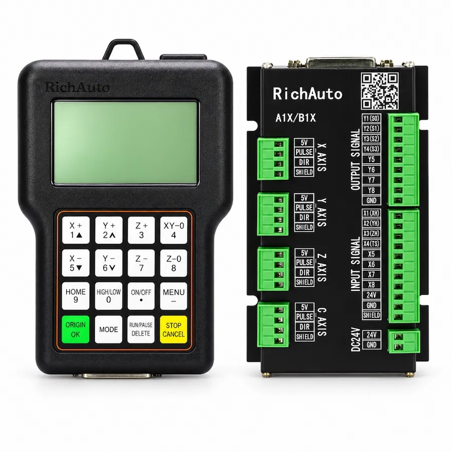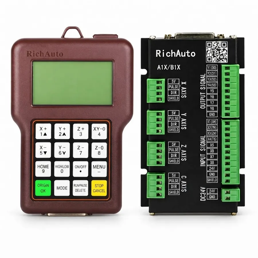
A RichAuto wiring diagram is a document for one board revision, not a universal map. The controller label tells you which range you have; the interface board tells you how the signals leave it. Reading the diagram without confirming the board is how a routine installation acquires a damaged output or an intermittent limit fault.
This guide walks through the checks in the order that prevents damage: identify the hardware, separate the power rails, confirm the connector set, then verify each signal group against the machine. It applies to the A1X and B1X controller ranges, including the A11 three-axis controller and the A12 plasma controller, with the model-specific differences noted on each product page.
Identify the Board Before the Wire
The interface board carries the terminals for drives, limits, the spindle and the auxiliary inputs. Different boards support different signal types and different terminal layouts, and the same controller model can be supplied with more than one board.
Scroll horizontally to read all columns.
| Record | Where it is | Why it decides the wiring |
|---|---|---|
| Controller designation | Label on the controller or handle | Sets the range and the supported functions |
| Board marking | Printed on the interface board | Identifies the terminal layout |
| Connector set | Between handle and board | Determines the cable and pin assignment |
| Power input rating | Board terminal or supplied reference | Sets the voltage for the board rail |
| Handle supply | Handle connection | Separate from the board input |
| Drive signal type | Board terminals or drive documentation | Step/direction or analogue arrangement |
Record those six items before connecting anything. If the board marking is unreadable, photograph it under light from two directions rather than copying a number from a listing.
Separate the Power Rails
The interface-board input and the handle supply are different electrical points. A reference that shows a 24V board input and a 5V handle rail is not permission to connect 24V to the handle connection. Treat each rail as its own circuit with its own rating.
- Confirm the board input voltage from the board marking or the supplied reference.
- Confirm the handle supply separately, and check the connector keying before pushing it home.
- Check polarity at the terminal, not at the wire colour. Colour conventions change between machine builders.
- Verify the protective earth path to the cabinet before energising the control circuit.
A controlled first power-up is worth the extra ten minutes: energise the control circuit without the spindle running, confirm the display and the inputs, then enable motion. This isolates a wiring error before it can produce movement.
The 50-Pin Connection and the Signal Groups
The connector set between the handle and the interface board is often described as a 50-pin connection. The count is a useful identifier, but the assignment is board-specific. Work from the reference supplied for the board rather than from a pinout copied from another machine, even when the connector looks identical.
The signals group into a small number of functions:
Scroll horizontally to read all columns.
| Signal group | Typical function | What to verify |
|---|---|---|
| Axis drive outputs | Step and direction or analogue command | Signal type, common reference and shielding |
| Limit and home inputs | Travel protection and referencing | Input polarity, normally closed behaviour and noise immunity |
| Emergency stop | Removal of motion and spindle power | Independent circuit, not a display command |
| Tool setter input | Tool-length reference | Input type and repeatability |
| Spindle control | Start, stop and speed command | Voltage or digital interface expected by the drive |
| Auxiliary outputs | Dust collection, coolant, clamps | Load rating and suppression |
Each group has a failure mode that shows up as something else. A limit input with the wrong polarity can look like a failed axis; a spindle signal with the wrong interface can look like a faulty controller. Verify the group against the drive documentation before concluding that the controller is at fault.
Common Wiring Mistakes
Most installation problems come from a small set of errors, and each leaves a recognisable signature.
- Board power on the handle rail. The display may appear to work briefly before the handle or its supply fails. Check the rail before replacing anything.
- Signal common not shared. Step and direction outputs need a common reference with the drive. Without it the axis may move erratically or not at all.
- Limit inputs wired as normally open. The controller then reads a healthy circuit as a fault, or misses a fault entirely, depending on the configured logic.
- Spindle control matched by connector rather than by signal. A connector that fits does not establish a compatible control interface.
- Shielding connected at both ends. Circulating current then appears as noise on the input signals. Earth the shield at one end according to the machine builder’s arrangement.
- Emergency stop implemented only in software. The machine then depends on the controller to stop, which is not a safety function.
If the machine is being converted rather than repaired, treat the wiring as a new installation. The controller replacement checklist covers the evidence to record before removing the old unit, and the A12 plasma wiring checks cover the torch and arc-voltage side, which follows different rules from a routing spindle.
Input Checks That Prevent Most Faults
Limit, homing and tool-setter inputs deserve individual checks because their logic is easy to assume and hard to diagnose afterwards. Confirm the expected state with the machine at rest, then trigger each input and watch the display change.
A normally closed limit circuit reads as healthy when the wiring is intact and as a fault when the circuit opens. A normally open arrangement behaves the opposite way. If the controller is configured for one and the machine is wired for the other, the machine will either refuse to reference or fail to stop at the limit.
Check the tool setter with the same discipline. Trigger it by hand, confirm the input changes, then confirm the reference it produces repeats. An input that works but drifts produces parts that are consistently wrong in one direction, which is harder to trace than an input that fails outright.
Verify Before Running a Job
Commissioning is a sequence of confirmations, not a single power-up.
- Confirm each input changes state when the corresponding sensor is triggered, and that the display shows the change.
- Confirm each axis moves in the expected direction at low speed before testing travel limits.
- Confirm the emergency stop removes motion and spindle power, and that restart requires a deliberate action.
- Confirm the tool setter repeats within the tolerance the work requires.
- Confirm the spindle starts, stops and changes speed through the commanded interface.
- Run a short program in air before cutting material.
Record the final state of each check. That record is the baseline for the next service visit, and it shortens the next diagnosis considerably.
When the Diagram Does Not Match
If the supplied diagram does not match the board, stop and request the correct set. A diagram for a different revision can be close enough to appear plausible while assigning a signal to the wrong terminal, which is the most damaging kind of near match.
Send the controller label, the board marking, the connector photographs and the machine terminals. With those four items a supplier can confirm the correct set rather than infer it from the model name. The manual and firmware index lists the documents available for each model, and the controller not working guide covers the symptom-first path when a machine is already down.