


BEST FIT
Choose B15 if:
- The machine uses three-axis motion with selectable heads.
- The cylinder and spindle switching sequence can be matched.
- The supplied B1X interface suits the cabinet and drives.

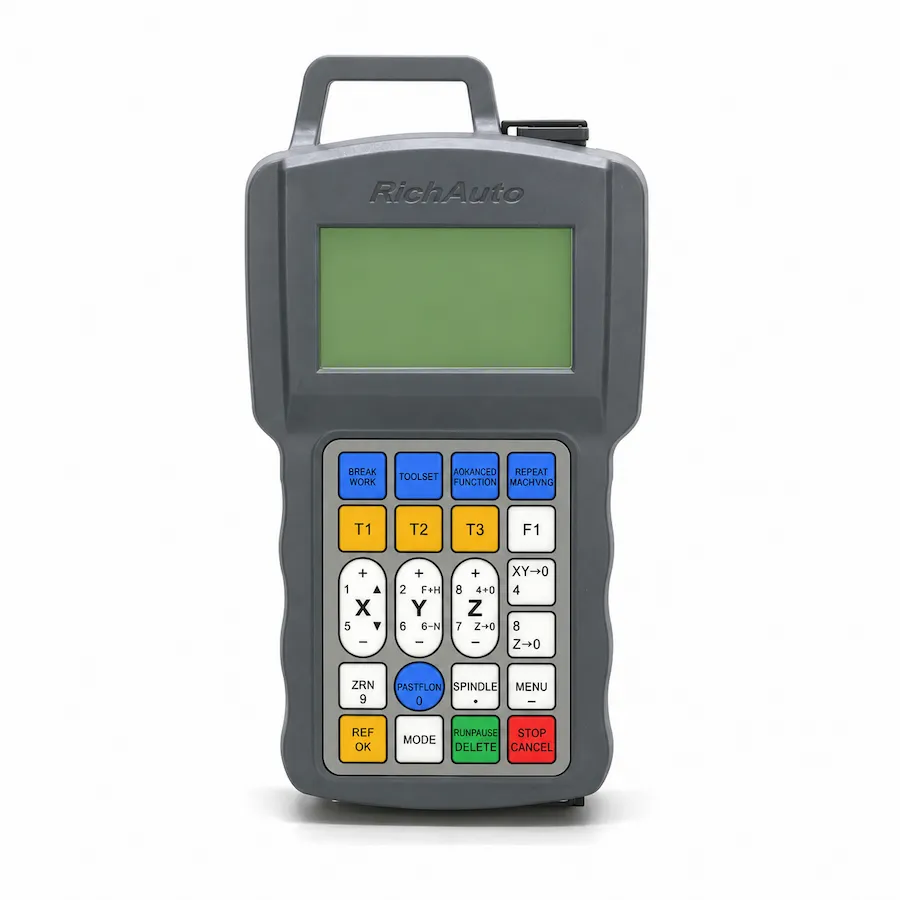
RichAuto B15 handheld controller front panel and keypad. Reference photo; confirm the supplied controller and interface-board revision.
B1X SERIES · RA-B15
Three-axis B1X DSP control for cylinder-operated multiple cutting heads, with the switching sequence checked against the machine.
Series: Browse the B1X controller range
CINKR supplies new, genuine RichAuto controllers and supports single-unit replacement orders. Eligible faults are covered by a one-year warranty. Most orders are dispatched within three working days after payment.
The supplied components, configuration, shipping cost and delivery estimate are confirmed in your quotation. Delivery, warranty and return terms.
PRODUCT GUIDE
Three-axis B1X DSP control for cylinder-operated multiple cutting heads, featuring 4.3-inch color LCD display and automated toolhead offset logic.
QUICK DECISION
BEST FIT
CHECK BEFORE ORDERING
CONSIDER ANOTHER MODEL IF
The RichAuto B15 is a high-performance three-axis DSP motion controller engineered specifically for multi-spindle CNC woodworking routers equipped with pneumatic head-switching slide cylinders. Widely deployed in high-volume cabinet production, architectural panel fabrication, and furniture manufacturing, multi-head machines eliminate manual tool changes by mounting multiple independent spindles along a single gantry beam.
Operating on the advanced B1X hardware platform, the B15 coordinates pneumatic head drop sequencing, calibrated coordinate offset compensation, and multi-speed inverter regulation. The 4.3-inch color LCD gives machine operators immediate visibility over active tool numbers, work coordinate systems, and feed overrides. Machining routines that combine heavy pocket hogging, fine profile carving, and vertical boring execute smoothly across dedicated cutters without manual operator intervention. Production facilities and machine builders can request a B15 quote configured for their exact pneumatic tooling arrangement.
Industrial multi-spindle routing centers frequently list controller models under B15, B15E, B15S, or B15C designations:
| Model Marking | Keypad Faceplate Language |
|---|---|
| B15 | Base multi-spindle B1X platform |
| B15E | English-only keypad faceplate (Export standard) |
| B15S | Bilingual (Chinese + English) keypad faceplate |
| B15C | Bilingual (Chinese + English) keypad faceplate |
All multi-spindle cylinder drop sequencing, 4.3-inch color graphic interface features, inverter speed controls, and firmware are identical across B15, B15E, B15S, and B15C. The only difference is the button faceplate language. An export B15E unit can replace a domestic B15S or B15C controller without rewiring pneumatic valves or inverter leads. Check your gantry cylinder configurations, then request an engineering quote.
Each standard RichAuto B15 control system includes the complete hardware complement necessary for machine cabinet installation:
Verify all screw terminal blocks and cable strain reliefs prior to cabinet commissioning.
Precision multi-head routing requires rigorous mechanical and coordinate alignment:
Ensure your CAM post-processor outputs standard tool change commands corresponding with B15 register mapping.
Field connections terminate at the B1X interface board inside the electrical enclosure. The board clearly segregates inductive solenoid outputs from sensitive drive pulses:
| Terminal Group | Terminal Identification | Controlled Device / Signal | Electrical Type |
|---|---|---|---|
| Cylinder Solenoids | Y01, Y02, Y03, Y04 | Solenoid valves for Head 1, 2, 3, 4 | 24V sinking transistor / relay outputs |
| Spindle Inverter Runs | FWD1, FWD2, FWD3 | Forward run command relays per head | Dry contact / optically isolated outputs |
| Multi-Speed Binary | S0, S1, S2, GND | Digital multi-step inverter speed selection | 24V isolated digital outputs |
| Motor Pulse/Dir | J2, J3, J4, J5 (PUL/DIR pairs) | Differential drive signals for X, Y, Z axes | 5V RS-422 differential driver channels |
| Sensor Inputs | X01 through X16 | Limit switches, home sensors, cylinder reeds | 24V optically isolated NPN sinking inputs |
| Auxiliary Analog Out | DA1, GND | 0-10V analog spindle speed reference | Isolated proportional analog output |
Connecting inductive solenoid coils requires flyback protection diodes or pre-suppressed 24V DC solenoid blocks to prevent electrical noise from disturbing motion interpolation circuits.
Reliable multi-head operation demands complete sensor feedback during every head transition:
Regular preventative maintenance of pneumatic lubricators and air filter bowls guarantees repeatable cylinder cycling over hundreds of thousands of panel operations. To inspect cabinet schematics or discuss multi-spindle drop logic, submit your machine specifications.
When upgrading from the older monochrome A15 or replacing an in-service B15 unit:
Submit your current cabinet terminal photographs through our engineering quote portal for a verified compatibility review.
Pneumatic reliability is the foundation of continuous multi-spindle router performance:
Proper pneumatic system design guarantees smooth, quiet spindle transitions across hundreds of thousands of panel production cycles.
Diagnostic alerts on the 4.3-inch color screen guide troubleshooting across pneumatic and electrical subsystems:
| Screen Diagnostic | Underlying Machine Condition | Verification Procedure |
|---|---|---|
| Cylinder Timeout Alert | Pneumatic cylinder failed to lower or raise within delay limit | Inspect compressed air pressure (min. 0.6 MPa); check magnetic reed sensors |
| Spindle Interlock Warning | Spindle rotation commanded while cylinder not fully lowered | Verify 24V auxiliary power to solenoid valves; inspect valve manifold |
| Axis Limit Encountered | Offset toolpath commanded axis past physical software boundaries | Verify coordinate offset parameters; check workpiece zero positioning |
| Inverter Fault Signal | Spindle inverter tripped on overload or thermal threshold | Inspect inverter error panel; examine spindle water cooling flow |
| Pulse Frequency Error | Commanded feedrate exceeds 2.0 MHz pulse rate ceiling | Lower rapid traverse speeds or reduce motor drive microstepping divisor |
Maintaining clean compressed air and lubricated slide rails resolves most mechanical cylinder switching delays.
For woodworking facilities evaluating multi-tool control architectures:
SELECTION CHECKLIST
SPECIFICATIONS
Compare the current B1X platform below. For an existing machine, match the controller label, interface board and software version; reference documents and photos may show earlier hardware.
| Product model | B15 |
|---|---|
| Series | B1X |
| CPU | DSP |
| Internal memory | Ask CINKR for the memory capacity of the supplied controller. |
| Display | 4.3-inch |
| Communication | USB / TCP/IP |
| Controlled axes | 3 axes |
| Control signal | Differential |
| Drive system | Stepper / Servo — Match the supplied hardware and software version. |
| Inputs | 16 inputs |
| Outputs | 16 outputs |
| Additional I/O | Confirm the board variant and available terminals for additional I/O. |
| Minimum input unit | 0.001 mm |
| Max. pulse frequency | 2 MHz |
| Power supply | 24V DC — Interface-board input; check its rating separately from the handle supply. |
| Interpolation | Request the interpolation details for the supplied software. |
| Breakpoint resume | Request the operating instructions for the supplied B1X software. |
| Power-failure recovery | Request the recovery instructions for the supplied B1X software. |
| Soft / hard limit | Confirm the limit and protection configuration with the machine builder. |
| Password protection | Request the protection and access settings for the supplied software. |
| Rotary axis | Not supported |
| ATC support | Not supported |
| Multi-spindle / cylinders | Supported |
| Plasma control | Not supported |
| Handwheel / MPG | Supported |
| Network communication | Supported — Match the supplied network interface and transfer workflow. |
COMPARE RELATED CONTROLLERS
Compare current platform applications, axes, display and I/O. Match the supplied board before replacement; earlier hardware may differ.
| Model | Main use | Axes | Display | I/O | Relationship |
|---|---|---|---|---|---|
| B15 | Three-axis cylinder and head switching | 3-axis | 4.3-inch | 16 inputs / 16 outputs | Selected model |
| A15 | Three-axis multi-head switching | 3-axis | 3-inch | 8 inputs / 8 outputs | Same-class option — compare functions, wiring and signals. |
| B57 | Three-axis automatic tool changing | 3-axis | 5-inch | 16 inputs / 16 outputs | Different platform — not a direct replacement. Machine-level compatibility check required. |
B15 alternatives depend on the required motion and machine functions. A related model is not a promise of interchangeable wiring or firmware.
DOWNLOADS
Download reference documents below. Match the controller and interface-board revision before using any wiring instructions. For a replacement or new order, request the documents for the exact supplied hardware from CINKR.
Reference wiring diagrams with English labels and signal notation. Confirm the matching board revision before using them.
Free direct downloadFAQ
The B15 interface breakout board supports independent pneumatic cylinder drop outputs and coordinate offset management for up to four motorized spindle heads.
The B15 incorporates a 4.3-inch color LCD screen for clear visual tracking of active toolhead numbers, differential motor drive signaling with 2.0 MHz pulse rates, and expanded 16-input / 16-output terminal blocks, compared to the 3-inch monochrome common-anode A15.
Yes. The B15 combines discrete multi-step binary speed outputs with independent spindle run relays, allowing each cutting head to operate at its optimized cutting RPM when lowered into position.
Document the number of operating spindles, pneumatic cylinder valve voltage ratings, drive signal format, and breakout board terminal wiring. Submit photos through our quote form.
The 4.3-inch color screen displays dynamic graphic indicators highlighting which spindle cylinder is actively deployed and cutting in real time.
Yes. All B15 models provide four optically isolated 24V sinking transistor outputs for pneumatic solenoid valve actuation.
Verify solenoid valve coil voltage (24V DC versus AC power), cylinder reed sensor polarities, and spindle center-to-center offset spacing.
REQUEST A QUOTE
Tell us the quantity and destination country. For a replacement or upgrade, include any available machine details below. This form only prepares your message; nothing is submitted or stored.