


BEST FIT
Choose A15 if:
- The machine uses three-axis motion with selectable heads.
- The required cylinder and spindle switching sequence is documented.
- The matching A1X board supports the machine connections.

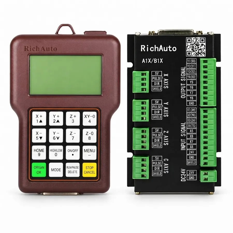
RichAuto A15 handheld controller and interface board. Reference photo; confirm the supplied controller and interface-board revision.
A1X SERIES · RA-A15
Three-axis A1X DSP control for cylinder-operated cutting heads, with tool-selection and position-offset requirements checked before ordering.
Series: Browse the A1X controller range
CINKR supplies new, genuine RichAuto controllers and supports single-unit replacement orders. Eligible faults are covered by a one-year warranty. Most orders are dispatched within three working days after payment.
The supplied components, configuration, shipping cost and delivery estimate are confirmed in your quotation. Delivery, warranty and return terms.
PRODUCT GUIDE
Three-axis DSP control for multiple cylinder-switched spindle heads; verify pneumatic sequencing, coordinate tool offsets and cabinet wiring.
QUICK DECISION
BEST FIT
CHECK BEFORE ORDERING
CONSIDER ANOTHER MODEL IF
The RichAuto A15 is an industrial three-axis DSP handheld motion controller engineered specifically for multi-spindle woodworking CNC routers and panel processing machinery. Widely utilized in custom cabinetry, architectural millwork, passage door manufacturing, and store fixture production, multi-spindle routers mount two, three, or four motorized spindle heads along a common gantry beam. Each spindle is mounted to an independent vertical pneumatic slide cylinder.
Rather than enduring prolonged production downtime while operators manually change collets and re-zero cutter lengths on single-spindle machines, the A15 executes instant tool changeovers by actuating pneumatic drop cylinders on the fly. Programmed tool change commands (T1, T2, T3, T4) automatically retract the previously running spindle, lower the requested toolhead, apply calibrated spatial coordinate offsets, and adjust inverter cutting speeds. Operating entirely without tethered personal computers, the A15 delivers robust daily performance immune to industrial dust and electrical noise. Machine builders and cabinet shops can request an A15 quote configured for their exact pneumatic tooling arrangement.
In high-volume cabinet production facilities, multi-spindle routers are encountered bearing model tags such as A15, A15E, A15S, or A15C. These model variations denote faceplate button languages:
| Model Marking | Keypad Faceplate Language |
|---|---|
| A15 | Base multi-spindle pneumatic motion platform |
| A15E | English-only keypad faceplate (Export standard) |
| A15S | Bilingual (Chinese + English) keypad faceplate |
| A15C | Bilingual (Chinese + English) keypad faceplate |
All pneumatic cylinder drop sequencing, spindle multi-speed logic, coordinate offset registers, and firmware are identical across A15, A15E, A15S, and A15C. The only distinction is the silkscreen language on the keypad buttons. Review your gantry pneumatic tooling requirements, then request an A15 quotation.
The standard RichAuto A15 multi-spindle control system arrives complete with industrial components prepared for electrical enclosure integration:
Inspect all terminal screw blocks and cable strain relief boots upon receipt to ensure mechanical integrity prior to cabinet commissioning.
Operating multiple spindles on a shared gantry frequently requires running diverse cutting tool geometries. For example, Head 1 may drive a 1/2-inch diamond surfacing cutter at 12,000 RPM, Head 2 runs a 5mm boring bit at 6,000 RPM, and Head 3 turns a 3/8-inch compression spiral at 18,000 RPM. The A15 manages spindle rotation through two primary methods:
Review your inverter technical manual to configure multi-step digital speed inputs according to the A15 output truth table.
High-precision multi-spindle machining requires rigorous coordinate alignment between cutting heads:
Document these calibrated offset dimensions before replacing an existing unit or performing firmware updates. To inspect terminal schematics or verify cylinder offset logic for your machinery, request an A15 wiring review.
Cabinet wiring for the A15 terminates at the intermediate interface breakout card inside the electrical cabinet. The board clearly segregates inductive pneumatic solenoid lines from low-voltage motion logic:
| Terminal Group | Terminal Identifier | Connected Field Signal | Electrical Characteristic |
|---|---|---|---|
| Cylinder Outputs | Y1, Y2, Y3, Y4 | Pneumatic cylinder lower/raise solenoid valves | 24V sinking transistor / relay outputs |
| Spindle Speed Select | S0, S1, S2, GND (J7) | Binary multi-speed frequency selection to inverter | 24V optically isolated digital outputs |
| Axis Motion Outputs | X-PUL, Y-PUL, Z-PUL | Step command outputs to axis drives | High-speed common-anode optical isolators |
| Axis Direction Lines | X-DIR, Y-DIR, Z-DIR | Direction command outputs to axis drives | High-speed common-anode optical isolators |
| Machine Reference Sensors | X0, Y0, Z0, Limit | Homing sensors and overtravel microswitches | Compatible with 24V NPN proximity switches |
| Tool Setting Touch Plate | Cutter / Tool Sensor | Automated tool length sensor block input | Optically isolated digital input channel |
To verify that your pneumatic solenoid valves do not exceed breakout board output current ratings, submit your electrical schematic for engineering review.
Operational safety on multi-head machinery requires strict sequence discipline during tool transitions:
Maintaining regular inspection of pneumatic regulator bowls and air filter elements ensures consistent, repeatable head actuation throughout high-cycle production shifts.
When commissioning or maintaining an A15 multi-spindle router, diagnostic alerts displayed on the handheld screen guide rapid fault isolation:
| Screen Diagnostic | Underlying Machine Condition | Systematic Troubleshooting Steps |
|---|---|---|
| Cylinder Down Fault | Drop cylinder failed to trigger down-position reed switch | Inspect shop air pressure (min. 0.6 MPa); check magnetic reed sensor alignment |
| Spindle Interlock Warning | Spindle rotation commanded while cylinder not locked down | Verify 24V auxiliary power to solenoid manifold; inspect pneumatic air lines |
| Axis Boundary Overrun | Toolhead offset shifted programmed path past physical travel | Verify coordinate offset parameters; check workpiece zero positioning |
| Tool Call Not Found | G-code program requested tool number outside configured range | Ensure CAM post-processor outputs only tool numbers T1 through T4 |
| Step Pulse Frequency Error | Feedrate commanded higher than 1.0 MHz output capacity | Reduce rapid traverse speed parameters in the machine configuration menu |
| Emergency Loop Open | Safety circuit interrupted or e-stop button engaged | Check continuity across cabinet safety relays and gantry stop buttons |
Maintaining dry, lubricated compressed air and clean vertical guide ways eliminates the vast majority of operational interruptions on multi-head equipment.
To order a matching replacement RichAuto A15 controller, gather the following technical data from your machinery:
Submit your machine data through our A15 quotation portal for engineering review.
For woodworking facilities evaluating multi-tool control architectures across the RichAuto family:
SELECTION CHECKLIST
SPECIFICATIONS
Compare the current A1X platform below. For an existing machine, match the controller label, interface board and software version; reference documents and photos may show earlier hardware.
| Product model | A15 |
|---|---|
| Series | A1X |
| CPU | DSP |
| Internal memory | 512 MB |
| Display | 3-inch |
| Communication | USB flash drive / USB cable — Match the supplied hardware and software version. |
| Controlled axes | 3 axes |
| Control signal | Common-anode |
| Drive system | Stepper / Servo — Match the supplied hardware and software version. |
| Inputs | 8 inputs |
| Outputs | 8 outputs |
| Additional I/O | Confirm the board variant and available terminals for additional I/O. |
| Minimum input unit | 0.001 mm |
| Max. pulse frequency | 1 MHz |
| Power supply | 24V DC — Interface-board input; check its rating separately from the handle supply. |
| Interpolation | Line / Arc / Curve — Match the supplied hardware and software version. |
| Breakpoint resume | Supported — Match the supplied hardware and software version. |
| Power-failure recovery | Supported — Match the supplied hardware and software version. |
| Soft / hard limit | Supported — Match the supplied hardware and software version. |
| Password protection | Supported — Match the supplied hardware and software version. |
| Rotary axis | Not supported |
| ATC support | Not supported |
| Multi-spindle / cylinders | Supported |
| Plasma control | Not supported |
| Handwheel / MPG | Not supported — Match the supplied hardware and software version. |
| Network communication | Not supported — Match the supplied hardware and software version. |
COMPARE RELATED CONTROLLERS
Compare current platform applications, axes, display and I/O. Match the supplied board before replacement; earlier hardware may differ.
| Model | Main use | Axes | Display | I/O | Relationship |
|---|---|---|---|---|---|
| A15 | Three-axis multi-head switching | 3-axis | 3-inch | 8 inputs / 8 outputs | Selected model |
| B15 | Three-axis cylinder and head switching | 3-axis | 4.3-inch | 16 inputs / 16 outputs | Same-class option — compare functions, wiring and signals. |
| B57 | Three-axis automatic tool changing | 3-axis | 5-inch | 16 inputs / 16 outputs | Different platform — not a direct replacement. Machine-level compatibility check required. |
A15 alternatives depend on the required motion and machine functions. A related model is not a promise of interchangeable wiring or firmware.
DOWNLOADS
Download reference documents below. Match the controller and interface-board revision before using any wiring instructions. For a replacement or new order, request the documents for the exact supplied hardware from CINKR.
Reference instructions and parameter guidance, mainly in English with some Chinese labels. These reference editions may describe earlier hardware; the supplied unit must match the document.
Free direct downloadFAQ
The A15 manages multiple cutting heads (typically 2, 3, or 4 independent spindles) mounted on pneumatic slide cylinders. When a tool change command executes in G-code, the A15 automatically raises the active cylinder, actuates the solenoid valve to lower the designated spindle, applies programmed X/Y/Z position offsets, and commands the proper inverter speed.
No. The A15 is designed for pneumatic multi-head switching rather than carousel or linear tool rack automatic tool changers. For single-spindle machines using motorized drawbars and toolholder magazines (such as ISO30 or BT30 cones), select the RichAuto B57 series instead.
Multiple-speed mode uses combinations of discrete digital output relays to trigger pre-configured frequency presets inside the spindle inverter. This eliminates the need for external analog 0-10V converter modules while supporting independent spindle speeds across different heads.
The standard A15 interface board provides hardware outputs supporting independent switching for up to four pneumatic cylinders, paired with coordinate offset registers in the handheld software.
Document the number of operating heads, cylinder valve solenoid voltages, inverter control wiring, and motor drive types. Share photos of the cabinet interface board through our quote portal.
Yes. Both models provide the exact same four-cylinder solenoid driver outputs (Y1 through Y4) and coordinate offset registers for multiple cutting heads.
Machine builders frequently install A15C or A15S bilingual units during factory assembly. When exporting to international buyers, the operating firmware is switched to English.
No, provided parameters are backed up via USB flash drive and restored to the replacement unit prior to production cutting.
REQUEST A QUOTE
Tell us the quantity and destination country. For a replacement or upgrade, include any available machine details below. This form only prepares your message; nothing is submitted or stored.