


BEST FIT
Choose A18 if:
- The machine requires a controlled rotary axis.
- The intended motion and CAM output fit the supplied A18 software.
- An A1X handheld workflow meets the operating needs.

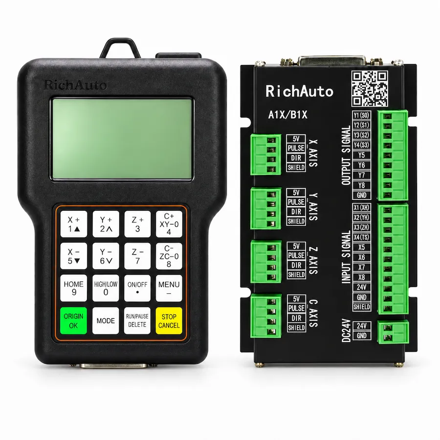
RichAuto A18 handheld controller and interface board. Reference photo; confirm the supplied controller and interface-board revision.
A1X SERIES · RA-A18
Four-axis A1X DSP control for rotary carving and machining, with the motion setup and board interface checked before purchase.
Series: Browse the A1X controller range
CINKR supplies new, genuine RichAuto controllers and supports single-unit replacement orders. Eligible faults are covered by a one-year warranty. Most orders are dispatched within three working days after payment.
The supplied components, configuration, shipping cost and delivery estimate are confirmed in your quotation. Delivery, warranty and return terms.
PRODUCT GUIDE
Four-axis DSP control for rotary carving and machining, also listed as A18E or A18S; confirm the fourth-axis marking, board version and rotary wiring.
QUICK DECISION
BEST FIT
CHECK BEFORE ORDERING
CONSIDER ANOTHER MODEL IF
The RichAuto A18 is an industrial standalone DSP motion controller engineered specifically for four-axis CNC routers, rotary woodcarving tables, and multi-axis stone milling equipment. Widely utilized in the production of decorative architectural columns, ornamental table legs, musical instrument bodies, and complex 3D artistic sculptures, the A18 delivers synchronized coordinate motion across four independent mechanical axes without tethering machinery to personal computer workstations on the shop floor.
Equipped with four coordinated motion channels (X, Y, Z, and A), the A18 supports both continuous four-axis simultaneous machining and indexed rotary operations (3+1 machining). By executing interpolation routines directly on a dedicated high-speed processor, the A18 eliminates communication latency and operating system interruptions. Operators maintain complete control over rotary feed overrides, coordinate display angles, and manual jogging directly from an ergonomic handheld pendant. Before commissioning an equipment upgrade or replacing an installed unit, review mechanical reduction and driver interface requirements, or request an A18 quote from CINKR.
In machine supply channels, equipment manuals, and listings, buyers encounter various model labels including A18, A18E, A18S, and A18C. These designations identify faceplate language variants of the standard four-axis A18 motion controller:
| Model Marking | Keypad Faceplate Language |
|---|---|
| A18 | Base 4-axis motion controller designation |
| A18E | English-only keypad faceplate (Export standard) |
| A18S | Bilingual (Chinese + English) keypad faceplate |
| A18C | Bilingual (Chinese + English) keypad faceplate |
All four-axis simultaneous rotary interpolation, 3+1 rotational positioning routines, pulse frequencies, and breakout board connections are identical across A18, A18E, A18S, and A18C. The only difference is the button faceplate language. When replacing an existing controller, confirm your rotary axis reduction ratio, then request an A18 quote.
Standard RichAuto A18 four-axis packages include the necessary hardware elements for control cabinet wiring:
Inspect all terminal screws and cable boots upon delivery to ensure reliable physical installation.
When programming the A18 for four-axis production, understanding your mechanical configuration determines correct operating parameters:
Select the kinematic mode matching your CAM toolpath generation strategy before setting work zero coordinates. To evaluate rotational clearance and mechanical tailstock alignment for your machine design, request a technical review.
Wiring the A18 requires careful terminal mapping at the cabinet interface board. The breakout board provides high-speed optical isolators delivering step and direction pulses to all four motor drives:
| Terminal Label | Associated Axis | Signal Purpose | Output Specification |
|---|---|---|---|
| X-PUL / X-DIR | X Axis (Gantry / Carriage) | Motion pulse and direction signals | Common-anode (+5V bus) |
| Y-PUL / Y-DIR | Y Axis (Table / Gantry Long) | Motion pulse and direction signals | Common-anode (+5V bus) |
| Z-PUL / Z-DIR | Z Axis (Vertical Lifter) | Motion pulse and direction signals | Common-anode (+5V bus) |
| A-PUL / A-DIR | A Axis (Rotary Chuck / 4th) | Rotary pulse and direction signals | Common-anode (+5V bus) |
| S0, S1, S2, GND | Spindle Inverter | Discrete multi-speed frequency control | 24V isolated digital outputs |
| 24V+, GND | Primary Board Power | Auxiliary DC logic and input power supply | 24V DC regulated input |
To calculate the pulse equivalent parameter for the fourth axis, apply the following standard formula:
Pulse Equivalent = (Drive Microsteps * Motor Steps per Rev * Gear Reduction Ratio) / 360
For example, a standard 1.8-degree stepper motor (200 steps per revolution) paired with a digital drive set to 1600 microsteps per revolution and driving a rotary chuck through a 4:1 reduction timing belt gearbox yields:
(1600 * 4) / 360 = 17.7777 steps per degree.
Entering this exact value into the A18 pulse parameter menu guarantees that commanded 360-degree rotations correspond perfectly with physical workpiece rotation.
Achieving uniform 3D carving without step artifacts requires rigorous mechanical alignment:
Documenting these calibration dimensions ensures repeatable part geometry across multi-piece production batches.
Four-axis CNC machinery incorporating motorized rotary chucks introduces complex cable routing challenges across gantry drag chains:
Preventing capacitive noise coupling into the A-axis step and direction lines ensures smooth, continuous rotary contouring free from angular position drift.
Diagnostic warnings on the A18 display assist technicians in isolating wiring faults and motion limit triggers:
| On-Screen Diagnostic | Root Cause Condition | Inspection Procedure |
|---|---|---|
| A-Axis Limit Overrun | Rotary axis commanded beyond configured software travel bounds | Check angular limit values in machine parameters; switch to manual jog to clear |
| Pulse Overfrequency Alert | Feedrate set higher than 1.0 MHz output capacity | Lower rapid traverse speed or reduce drive microstepping divisor |
| Spindle Inverter Fault | Spindle drive error contact signaled to controller | Inspect inverter error panel; examine run command relay wiring |
| Emergency Stop Active | E-stop button depressed or safety loop broken | Verify 24V continuity through normally-closed emergency stop pushbuttons |
| Step Signal Loss | Loose terminal connection or broken cable shield | Tighten breakout board terminal screws; inspect 50-pin cable continuity |
Reviewing electrical circuit continuity before modifying controller parameters prevents configuration corruption.
When ordering an A18 controller to replace an existing unit, provide our technical staff with the following specifications:
Submit your machine information through our A18 quotation desk for complete engineering review.
For facilities evaluating multi-axis machine upgrades across the RichAuto family:
SELECTION CHECKLIST
SPECIFICATIONS
Compare the current A1X platform below. For an existing machine, match the controller label, interface board and software version; reference documents and photos may show earlier hardware.
| Product model | A18 |
|---|---|
| Series | A1X |
| CPU | DSP |
| Internal memory | 512 MB |
| Display | 3-inch |
| Communication | USB flash drive / USB cable — Match the supplied hardware and software version. |
| Controlled axes | 4 axes — Match the supplied hardware and software version. |
| Control signal | Common-anode |
| Drive system | Stepper / Servo — Match the supplied hardware and software version. |
| Inputs | 8 inputs |
| Outputs | 8 outputs |
| Additional I/O | Confirm the board variant and available terminals for additional I/O. |
| Minimum input unit | 0.001 mm |
| Max. pulse frequency | 1 MHz |
| Power supply | 24V DC — Interface-board input; check its rating separately from the handle supply. |
| Interpolation | Line / Arc / Curve — Match the supplied hardware and software version. |
| Breakpoint resume | Supported — Match the supplied hardware and software version. |
| Power-failure recovery | Supported — Match the supplied hardware and software version. |
| Soft / hard limit | Supported — Match the supplied hardware and software version. |
| Password protection | Supported — Match the supplied hardware and software version. |
| Rotary axis | Supported — Match the supplied hardware and software version. |
| ATC support | Not supported |
| Multi-spindle / cylinders | Not supported |
| Plasma control | Not supported |
| Handwheel / MPG | Not supported — Match the supplied hardware and software version. |
| Network communication | Not supported — Match the supplied hardware and software version. |
COMPARE RELATED CONTROLLERS
Compare current platform applications, axes, display and I/O. Match the supplied board before replacement; earlier hardware may differ.
| Model | Main use | Axes | Display | I/O | Relationship |
|---|---|---|---|---|---|
| A18 | Four-axis rotary carving | Confirm configuration | 3-inch | 8 inputs / 8 outputs | Selected model |
| B18 | Four-axis rotary machining | 4-axis | 4.3-inch | 16 inputs / 16 outputs | Same-class option — compare functions, wiring and signals. |
| B58 | Four-axis rotary machining with color preview | 4-axis | 5-inch | 16 inputs / 16 outputs | Same-class option — compare functions, wiring and signals. |
A18 alternatives depend on the required motion and machine functions. A related model is not a promise of interchangeable wiring or firmware.
DOWNLOADS
Download reference documents below. Match the controller and interface-board revision before using any wiring instructions. For a replacement or new order, request the documents for the exact supplied hardware from CINKR.
Reference instructions and parameter guidance, mainly in English with some Chinese labels. These reference editions may describe earlier hardware; the supplied unit must match the document.
Free direct downloadReference instructions and parameter guidance, mainly in English with some Chinese labels. These reference editions may describe earlier hardware; the supplied unit must match the document.
Free direct downloadFAQ
The A18 provides four independent motion axes (X, Y, Z, and A). It supports both continuous 4-axis simultaneous interpolation for complex 3D surface carving and indexed rotary positioning (3+1 machining), where the rotary axis locks at fixed angle intervals while the remaining axes machine flat features.
The A18E represents the English-interface designation of the A18 controller, featuring English faceplate buttons and default English menus. The A18S designation indicates internal component packaging or specific firmware batch codes. All share the identical 4-axis interpolation processor and 50-pin interface structure.
The fourth axis can be configured in linear millimeter mode (for tangential cutter tracking) or rotary angular degree mode (0 to 360 degrees). Pulse equivalent calculations must account for motor step angle, microstepping drive settings, and gearbox reduction ratios.
The A18 outputs common-anode (+5V common bus) step and direction pulse trains across all four axes, with a maximum pulse frequency of 1.0 MHz per axis.
Submit photographs of the handheld controller model sticker, the cabinet breakout board terminal labels, rotary axis gearbox reduction ratio, and motor drive model numbers through the CINKR quote form.
Yes. All A18 variants (A18, A18E, A18S, A18C) execute the identical four-axis simultaneous interpolation algorithms for continuous organic 3D carving and 3+1 rotational positioning.
A18E has strictly English button labels, while A18S has bilingual button labels. Software menus on both can be operated in complete English.
Record the motor step angle, drive microstep divisor, and gearbox reduction ratio to verify that pulses per degree align with existing tooling files.
REQUEST A QUOTE
Tell us the quantity and destination country. For a replacement or upgrade, include any available machine details below. This form only prepares your message; nothing is submitted or stored.