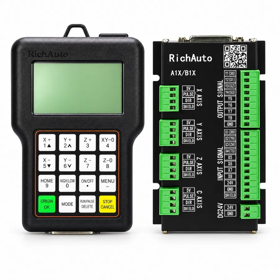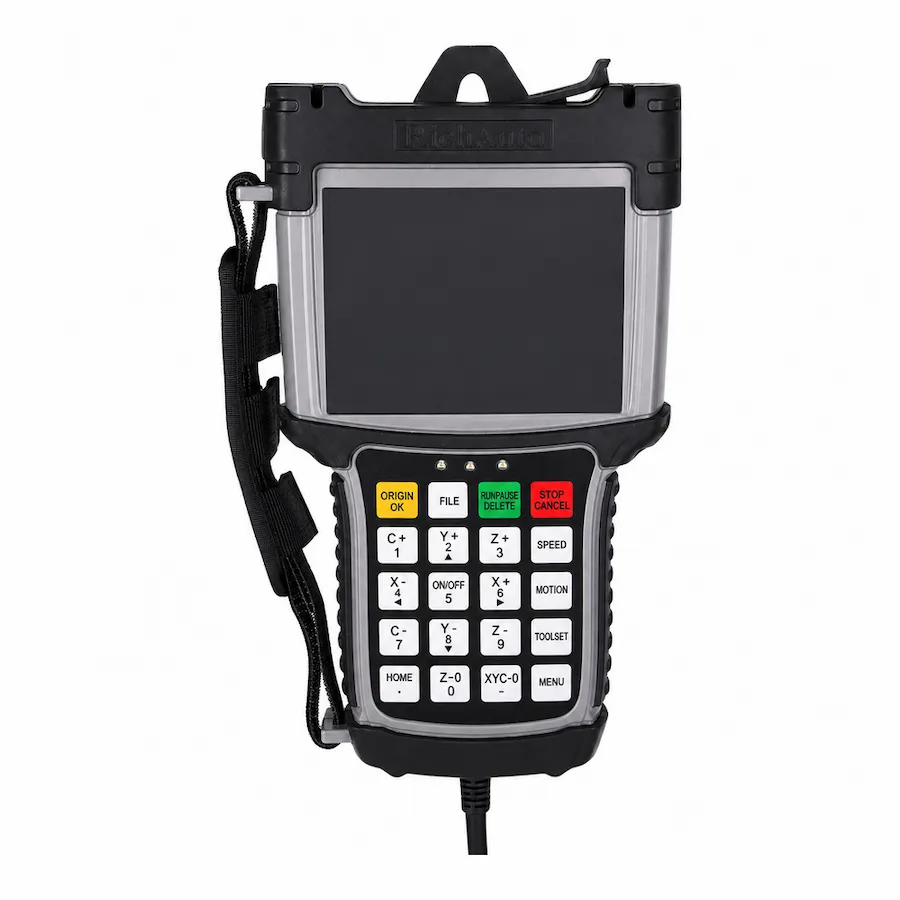
A DSP controller is a dedicated motion controller that runs a machining file on its own hardware, with a handheld unit or a small display as the operator interface. It is called offline because the computer that prepared the file is not connected while the machine cuts. The controller reads the file, generates the motion signals and reports position and status.
That definition is short, and it carries three practical consequences: the file has to be transferred before the job starts, the operator works with a machine-specific interface rather than a desktop, and the computer moves from the machining path to the preparation step. Understanding those consequences is more useful than memorising a specification.
What the Controller Includes
A working arrangement has four parts, and only one of them is the controller itself.
Scroll horizontally to read all columns.
| Part | Role | What to confirm |
|---|---|---|
| Controller and handheld | Runs the file, shows position and status | Model, version and axis support |
| Interface board | Carries the terminals for drives and I/O | Board revision and signal type |
| Drives or amplifiers | Deliver power to the motors | Signal compatibility and enable logic |
| File transfer | Moves the program to the controller | Removable media or network option |
The controller commands; it does not supply motor power. That distinction explains most installation questions. A controller output that switches correctly can still produce no motion if the drive is not enabled or the signal common is missing.
The Offline Workflow
The workflow has five steps, and each one has a place where mistakes are common.
- Design and toolpath. The part is modelled and toolpathed in CAM software, and a post processor produces the file the controller accepts.
- Transfer. The file is copied to removable media or sent over the optional network connection.
- Verify at the machine. The operator checks the file name, the program size and the work origin before running.
- Run. The controller executes the file, with feed override, single block and breakpoint recovery available at the handheld.
- Record. Parameters, tool references and any offsets are recorded so the next setup starts from a known state.
Step three is where most avoidable errors happen. A correct file run from the wrong work origin produces a correct cut in the wrong place, and the controller cannot detect that mistake for the operator.
What Happens During a Job
Once the file is loaded, the controller takes over the timing. It reads the program, generates the motion signals and updates the display as the axes move. The operator can change the feed override, pause at a block boundary and resume from a breakpoint after a stop.
That local execution is the practical meaning of offline. The computer that produced the file can be switched off, moved or used for the next job while the machine continues. For a workshop that prepares programs during the day and runs them in the evening, the separation is useful rather than theoretical.
It also makes the controller’s state the authoritative one. If a job stops, the position and the program line are on the controller, not in a software window on a PC. Recovery starts from what the controller shows.
Where the Controller Sits in the Signal Chain
The controller sits between the file and the drives. It receives a program, converts it into motion commands and passes those commands to the drives or amplifiers. The interface board carries the terminals, and the machine wiring connects them to the drives, the spindle and the sensors.
That position explains what the controller can and cannot detect. It can report the position it has commanded and the inputs it has received. It cannot see a slipping belt, a blunt cutter or a workpiece that moved. Those conditions appear as results, not as controller faults, which is why the first cut after a setup change is worth inspecting.
What a DSP Controller Is Not
Three confusions appear repeatedly in enquiries.
- It is not a PC. It does not run a desktop operating system, office software or CAD. It runs the machining file and the machine interface.
- It is not a drive. It sends motion signals; the drives deliver power. A drive fault looks like a controller fault until the drive status is checked.
- It is not CAM software. Toolpaths are prepared elsewhere. The controller’s job starts with the file, not with the model.
Keeping those three boundaries clear shortens both the buying decision and the fault diagnosis.
When an Offline Controller Fits
An offline arrangement suits machines where the operator works at the machine, the file workflow is simple and the machine must keep running without a PC. Routers, engravers and many production machines fit that description, and the A11 three-axis controller is a typical example.
It also suits environments where a PC would struggle. Dust, heat and vibration are unkind to desktop hardware. Removing the PC from the cutting path removes a class of failure that has nothing to do with the machining process.
It is a weaker fit when the workflow depends on a shared network, frequent program changes driven from an office, or software features that only exist on a desktop platform. Those cases can still use an offline controller, but the file transfer and version control need to be designed rather than assumed.
Display, Keypad and Daily Use
The interface is part of the controller, not an accessory. A handheld unit with a clear display lets the operator watch position and status while standing at the machine, and a keypad with machine-specific keys shortens the common actions.
Two details are worth confirming before ordering. The first is the keypad language, because a unit marked in a language the operator does not read slows every setup. The second is the display size and contrast in the light of the workshop, not in a photograph.
Neither detail changes the motion capability. Both change how often the operator has to walk to a computer to check something, which is the sort of cost that does not appear in a specification table.
Five Questions Before Choosing a Model
Scroll horizontally to read all columns.
| Question | Why it decides the model |
|---|---|
| How many axes must move together? | Three-axis and four-axis models are not interchangeable |
| What drive signal does the machine use? | Step and direction or analogue command changes the board |
| Does the machine change tools automatically? | ATC needs a model and a machine sequence that support it |
| How will files reach the machine? | Media or network option must match the workflow |
| Who operates it, and what do they need to see? | Display size and keypad language affect daily use |
Answer those five before comparing prices. A model that answers four of them and misses the drive signal is not a cheaper option; it is a return.
Common Misunderstandings
Two more assumptions are worth correcting. The first is that a larger display implies a more capable controller: display size and motion capability are separate. The second is that a familiar keypad means interchangeable wiring: keypad layout and board revision vary independently.
Both assumptions lead to the same outcome — a controller ordered by appearance rather than by interface. Confirm the board marking and the drive signal, then choose the model that supports them.
For a wider comparison of control arrangements, the DSP vs Mach3 vs NcStudio guide explains where each architecture places the trajectory. For a machine that is already installed and behaving badly, the controller not working guide starts from the symptom instead of the specification.